Hardware
An NTC thermistor and its divider as the driver uses them: the two terminals, the package families, the divider, the series resistor, the ADC input, self-heating and tolerances. Every number here is general or derived from the beta equation; the figures for one part are labelled "worked example" and come from a preset whose table rows are unverified (the vendor's sheet prints no table).
Datasheet sections this page relies on
- Voltage divider and the series resistor: Public references n/a n/a, Divider, V = V_s R_n / (R_s + R_n), p. 1
- Self-heating power: Public references n/a n/a, Dissipated power, P = V_s^2 R_n / (R_s + R_n)^2, p. 1
- Example part: package and ratings: TDK none printed Rev.3, Dimension and Construction; Electrical Characteristics: power, dissipation, current, voltage, range, p. 1
All of them, with the driver API for each: Datasheet map.
The part
A thermistor has two terminals and no polarity. Its resistance falls as it heats: for most parts roughly 3 to 5 % per kelvin near room temperature. The driver names the terminals T1 and T2 so the figures can draw them; neither the part nor the driver cares which is which.
Families, as examples and typical, not a datasheet claim (the package drawn is the 0603 chip family; sizes are family nominals, check your part):
| Family | Typical body | Seen as |
|---|---|---|
| Chip 0402, 0603, 0805 | About 1.0 x 0.5, 1.6 x 0.8 and 2.0 x 1.25 mm | Two end terminals, reflow |
| Glass bead, epoxy-coated disc | Millimetres, on two leads | Probes, panel and liquid sensing |
| Ring lug, probe assembly | Part plus cable | Two wires |
Common classes: R25 of 2.2, 4.7, 10, 47 or 100 kOhm; B of about 3000 to 4300 K; 1 to 5 % on R25 and 1 to 3 % on B;
rated ranges of about -40 to +125 or +150 degrees Celsius, higher for glass. The pinout, the package outline, the block
diagram and the two circuits below are drawn from docs/hardware.yml.
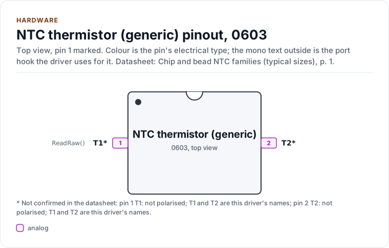
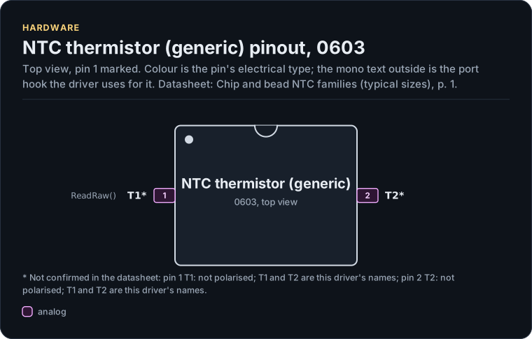
Figure description and sources
The NTC thermistor (generic) seen from the top, in its 0603 package. Pin 1 is marked by the dot; the numbers run counter-clockwise from it. Each pad is coloured by the pin's electrical type (legend below). Next to it is the pin's name and, in mono, the hook of the driver's port that drives or reads it; a pin without a hook is not used by the driver.
Drawn from: docs/hardware.yml; inc/ntc_thermistor.hpp; inc/ntc_thermistor_adc_interface.hpp.
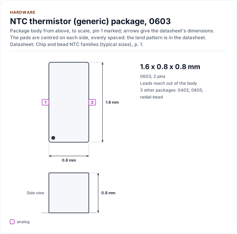
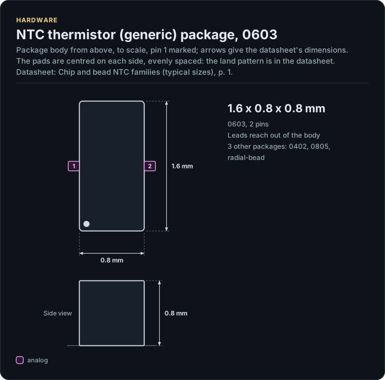
Figure description and sources
The NTC thermistor (generic) package seen from the top and, when the height is known, from the side, drawn to scale: 1.6 x 0.8 x 0.8 mm. The arrows carry the datasheet's dimensions, the dot marks pin 1 and the pads are numbered counter-clockwise from it, coloured by the pin's electrical type (legend below). Pads sit centred on each side, evenly spaced; the datasheet's land pattern is the reference for a board.
Drawn from: docs/hardware.yml; inc/ntc_thermistor.hpp; inc/ntc_thermistor_adc_interface.hpp.
0603, 2 pins (Chip and bead NTC families (typical sizes), p. 1).
| Pin | Name | Type (domain) | Function | Driver hook | Datasheet |
|---|---|---|---|---|---|
| 1 | T1 1 |
analog (VDD) | One terminal, not polarised: see the two circuits for the wiring | ReadRaw() |
Two-terminal resistor; terminals are not polarised, p. 1 |
| 2 | T2 2 |
analog (VDD) | The other terminal, not polarised: see the two circuits for the wiring | - | Two-terminal resistor; terminals are not polarised, p. 1 |
Source of this table and of the chip figures: docs/hardware.yml.
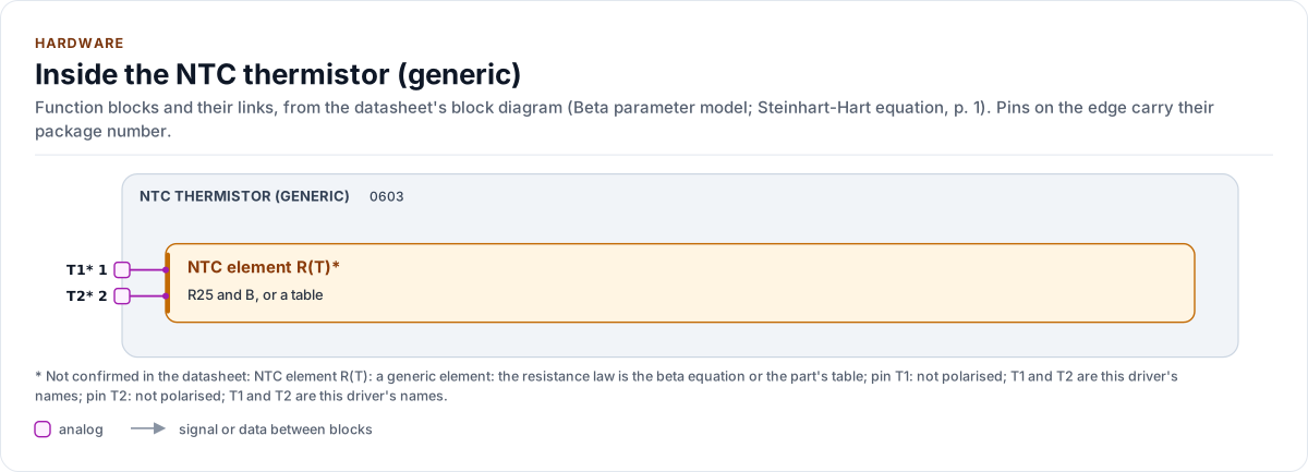
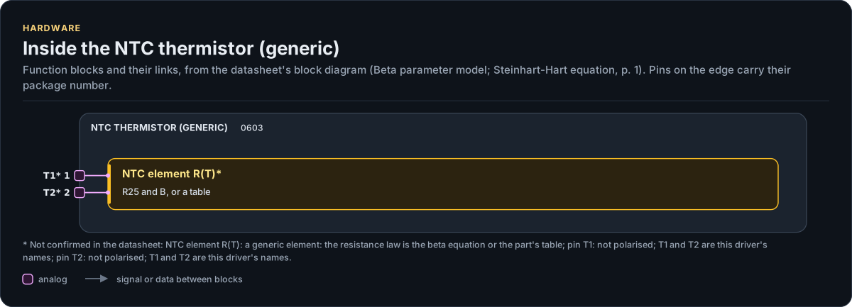
Figure description and sources
The NTC thermistor (generic)'s function blocks inside its outline. Arrows between blocks carry signals or data in the direction they point (both ways where they have two heads). The package pins stand on the left and right edges with their numbers, each wired to the block it reaches.
Drawn from: docs/hardware.yml; inc/ntc_thermistor.hpp; inc/ntc_thermistor_adc_interface.hpp.
The divider
The driver reads the node of a resistor divider. In low-side form (the thermistor to ground) the node falls as the part heats; in high-side form (the thermistor to the supply) it rises.
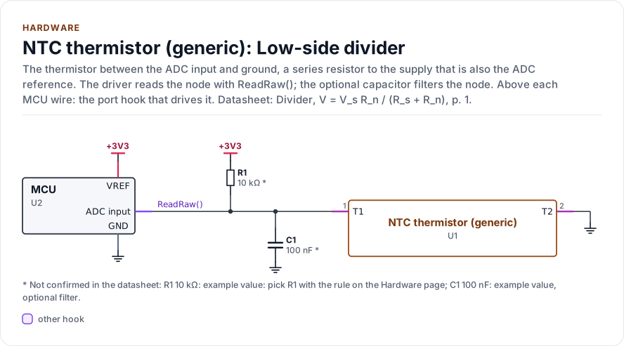
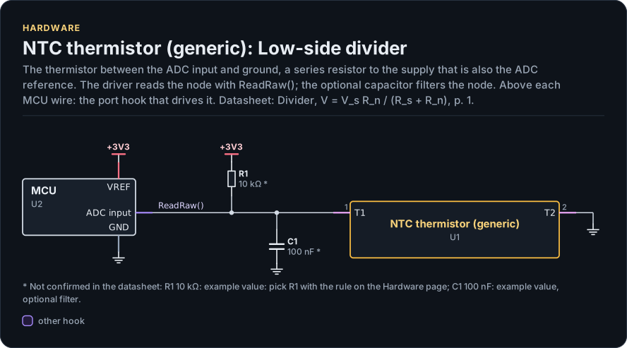
Figure description and sources
A schematic. The MCU is on the left, each of its pins level with the chip pin it connects to; above each wire is the hook of the driver's port that drives or reads it. Supply pins point up to their supply and decoupling, ground pins down. Pins on the right carry the loads and the pins tied to a supply or ground; a cross marks a pin left open. A dot is a junction; wires that cross without a dot are not connected.
Drawn from: docs/hardware.yml; inc/ntc_thermistor.hpp; inc/ntc_thermistor_adc_interface.hpp.
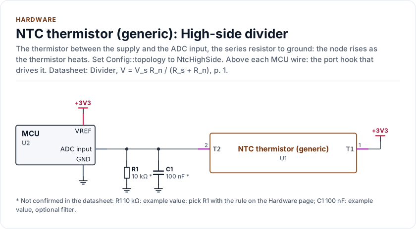
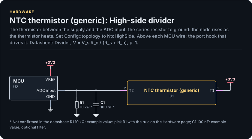
Figure description and sources
A schematic. The MCU is on the left, each of its pins level with the chip pin it connects to; above each wire is the hook of the driver's port that drives or reads it. Supply pins point up to their supply and decoupling, ground pins down. Pins on the right carry the loads and the pins tied to a supply or ground; a cross marks a pin left open. A dot is a junction; wires that cross without a dot are not connected.
Drawn from: docs/hardware.yml; inc/ntc_thermistor.hpp; inc/ntc_thermistor_adc_interface.hpp.
Low-side divider (figure chip-circuit-divider)
| Part | Kind | Value | Connects | Datasheet |
|---|---|---|---|---|
| U2 | MCU | - | VREF: +3V3, ADC_IN: NODE, GND: GND | Divider, V = V_s R_n / (R_s + R_n), p. 1 |
| R1 | resistor | 10 kΩ (not confirmed: example value: pick R1 with the rule on the Hardware page) | +3V3, NODE | Divider, V = V_s R_n / (R_s + R_n), p. 1 |
| C1 | capacitor | 100 nF (not confirmed: example value, optional filter) | NODE, GND | Divider, V = V_s R_n / (R_s + R_n), p. 1 |
High-side divider (figure chip-circuit-divider-high)
| Part | Kind | Value | Connects | Datasheet |
|---|---|---|---|---|
| U2 | MCU | - | VREF: +3V3, ADC_IN: NODE, GND: GND | Divider, V = V_s R_n / (R_s + R_n), p. 1 |
| R1 | resistor | 10 kΩ (not confirmed: example value: pick R1 with the rule on the Hardware page) | NODE, GND | Divider, V = V_s R_n / (R_s + R_n), p. 1 |
| C1 | capacitor | 100 nF (not confirmed: example value, optional filter) | NODE, GND | Divider, V = V_s R_n / (R_s + R_n), p. 1 |
Export a circuit for a schematic or PCB tool: kokeb-docs hardware --kicad-netlist OUT.net --circuit divider.
With Rs the series resistor and Rn the thermistor, the node's share of the supply is Rn / (Rs + Rn) low side and
Rs / (Rs + Rn) high side. Config::topology says which. If the ADC's reference is the divider's supply, the code
is a pure ratio and the supply drops out (ratiometric, the default). If it is not, declare both
adc_vref_mv and divider_supply_mv (see Configuration); declaring one without the other is
InvalidArgument.
Choosing the series resistor
The node moves most where Rn equals Rs, so put that at the middle of the range you care about. A good rule for a
whole range is the geometric mean:
Worked example (rows unverified): 188.5 kOhm at -40 and 313 Ohm at +150 give 7.7 kOhm; 10 kOhm centres the divider at
25 degrees Celsius instead and is the common choice. Round to the nearest value you can buy and give the driver the
real value in series_ohm (1 to 16 777 216 ohms), with its tolerance in series_tol_ppm so the bound includes it.
What an ADC step is worth
Near a divider's middle one ADC step is about T^2 / B / (r (1 - r)) / 2^bits kelvin, with r the node's share. It
is finest where r is 0.5 and coarsens toward the ends. Worked example, a 12-bit ADC, 10 kOhm series resistor and the
example preset (derived from its rows, which are unverified):
| Temperature (degC) | Resistance (ohm) | Code | One code is (K) |
|---|---|---|---|
| -35 | 144 300 | 3831 | 0.076 |
| 0 | 27 280 | 2997 | 0.028 |
| 25 | 10 000 | 2048 | 0.026 |
| 60 | 3 019 | 950 | 0.044 |
| 85 | 1 451 | 519 | 0.079 |
| 125 | 534 | 208 | 0.220 |
| 145 | 346 | 137 | 0.353 |
A 16-bit ADC divides these by 16. The driver carries resistance to 1/256 ohm inside, so its own rounding stays well below one code even at the hot end.
The ADC input
- Source impedance. The divider's output impedance is
Rsin parallel withRn, up toRs. Read your ADC's recommended source impedance; a high one needs a capacitor at the node, and averaging (sample_count) helps. - Filter and settling. 100 nF from the node to ground is a common start (a time constant of about 1 ms at 10 kOhm);
the thermistor is slow, so a slow filter costs nothing but start-up time. The node settles with the time constant
(Rs || Rn) x C, whereRnis the part's resistance at the cold end, so setsettle_usto at least five of them (5 ms for 10 kOhm and 100 nF), and check that the ADC's sampling capacitor charges through the source impedance within its sampling time. A bias switch is needed forsettle_usto mean anything: without one it is not allowed. - A cut wire. A broken wire between the node and the ADC pin leaves the input floating, and the driver cannot tell it from a temperature: a pull resistor at the pin, or a reading with the divider off, is yours.
- Range. The node must stay inside the ADC's input range; with separate supply and reference, choose
Rsso the node share times the supply stays below the reference. - Margins. A node within
open_margin_codesof the open rail readsOpenCircuit, withinshort_margin_codesof the short railShortCircuit(2 codes by default, 1 or more with separate supply and reference). The margins are in codes: size them to the noise of the node, a few codes at 12 bits, hundreds at 20 bits and wider.
Self-heating
The divider heats the thermistor: P = Vs^2 * Rn / (Rs + Rn)^2, at most Vs^2 / (4 Rs). The rise is P divided by
the part's dissipation constant in your mounting, in milliwatts per kelvin; about 1 mW/K is typical for a chip part on
a board (the worked example's sheet gives 1 mW/degC at 25 degrees Celsius), but yours comes from its datasheet and
your assembly. At 3.3 V with 10 kOhm and 10 kOhm that is 272 uW, about 0.27 K at 1 mW/K, which is ten ADC steps of the
worked example. SelfHeatingMicrowatts() computes P; the driver does not correct for it. To cut it, power the
divider from a GPIO only while sampling (SetBias(), see Porting), raise Rs, or lower the supply.
// How much a 3.3 V divider warms the part: P in microwatts, divided by the
// part's dissipation constant (about 1 mW/K for a chip part on a board: read
// your datasheet).
uint32_t SelfHeatingMillikelvin(uint32_t r_ntc_ohm, uint32_t dissipation_uw_per_k) {
  const ntc_thermistor::Config c{.curve = ntc_thermistor::presets::kTdkNtcg163jf103ft1s,
                                 .adc_vref_mv = 3300,
                                 .divider_supply_mv = 3300};
  const uint32_t microwatts = ntc_thermistor::SelfHeatingMicrowatts(c, r_ntc_ohm);
  return (microwatts * 1000U) / dissipation_uw_per_k; // 272 uW at 25 degC and 1000 uW/K: 272 mK
}
Tolerance
At temperature T (kelvin) a relative error dR/R in the resistance is a temperature error of
(T^2 / B) * (dR/R); at 25 degrees Celsius with B 3435 K, 1 % is 0.26 K. A B error matters away from the 25 degree
point: it is multiplied by ln(R/R0). Reading::uncertainty_mc adds these terms, the series resistor's tolerance
and one converter step.
Faults the divider cannot tell apart
A cut wire or missing part drives a low-side node to the supply rail: OpenCircuit. A shorted part drives it to ground:
ShortCircuit. A divider whose supply has collapsed also reads as a short on a low-side divider (the node is at
ground), and the driver has no second channel to tell them apart. If that matters, measure the supply on another
channel in your application.
Adapting hardware.yml and the card to your part
docs/hardware.yml describes a generic two-terminal part. To describe yours:
chip: the part's name.package: itstype, theoutlinefrom the part's drawing and thevariantsfrom its ordering table.- The
ntcblock'sdetail: R25 and B, or "table". - The circuits:
R1,C1and the supply of your divider. - Point each
refsentry at your datasheet (documentdsindocs/datasheets.yml: the section and the printed page) and delete eachunverifiedyou have confirmed.
Keep the pins T1 and T2 and the two hooks. Then run kokeb-docs hardware --check, kokeb-docs figures and
kokeb-docs gen: the pinout, the outline, the block diagram, the circuits and the README's chip card follow.