Figures
Every figure on this site is drawn by a Python module from facts extracted from the code, so it is rebuilt,
not redrawn, when the code changes. CI runs kokeb-docs figures --check and fails when a
committed figure no longer matches the code. Each figure below lists the files it is drawn from.
Inside the AS5047U
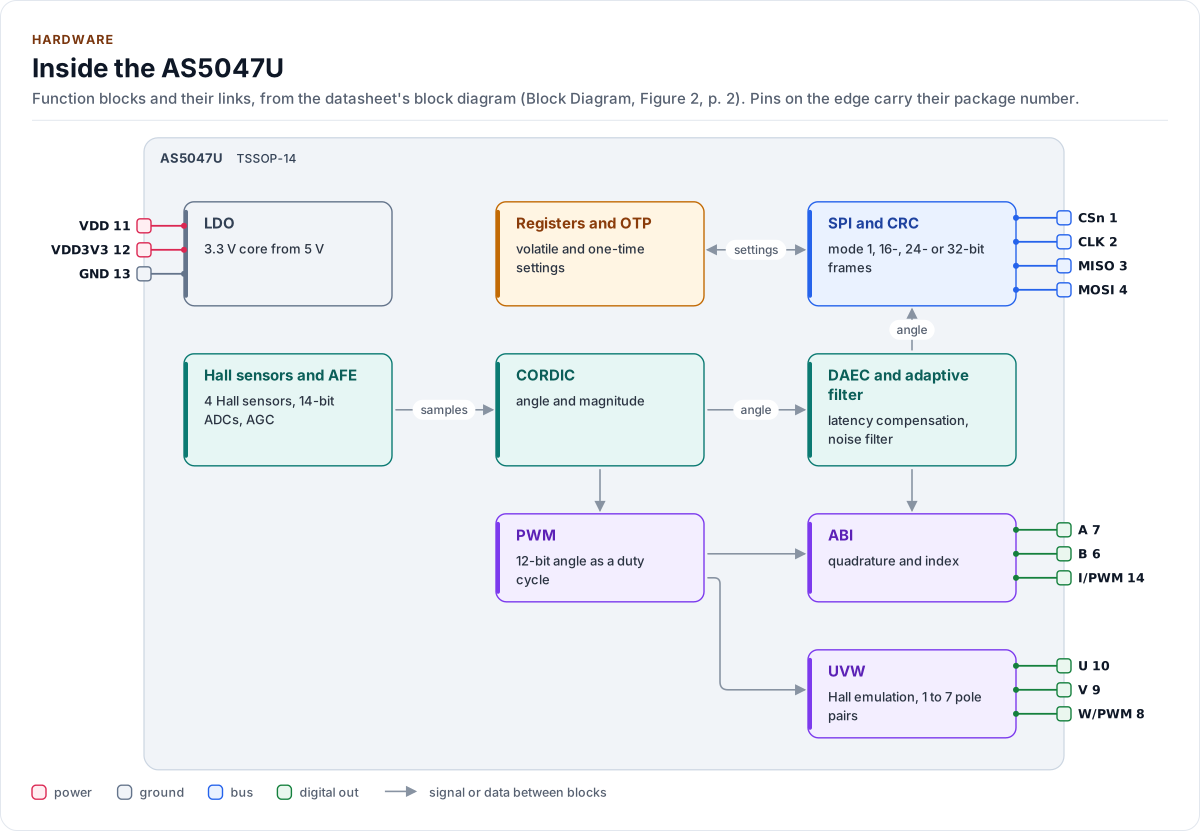
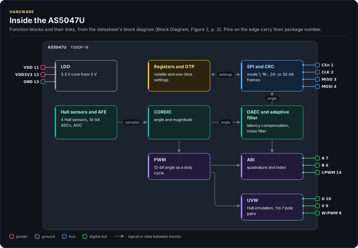
Figure description and sources
The AS5047U's function blocks inside its outline. Arrows between blocks carry signals or data in the direction they point (both ways where they have two heads). The package pins stand on the left and right edges with their numbers, each wired to the block it reaches.
Drawn from: docs/hardware.yml; inc/as5047u_spi_interface.hpp.
Hardware description: docs/hardware.yml
Drawn from:
AS5047U: 3.3 V operation
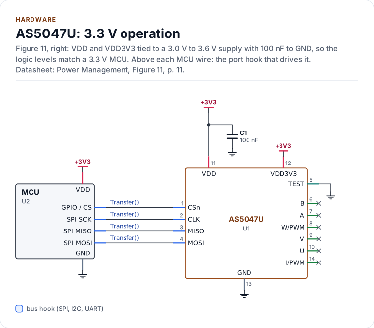
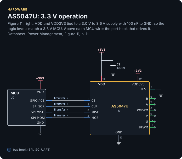
Figure description and sources
A schematic. The MCU is on the left, each of its pins level with the chip pin it connects to; above each wire is the hook of the driver's port that drives or reads it. Supply pins point up to their supply and decoupling, ground pins down. Pins on the right carry the loads and the pins tied to a supply or ground; a cross marks a pin left open. A dot is a junction; wires that cross without a dot are not connected.
Drawn from: docs/hardware.yml; inc/as5047u_spi_interface.hpp.
Hardware description: docs/hardware.yml
Drawn from:
AS5047U: Minimum circuit, 5 V
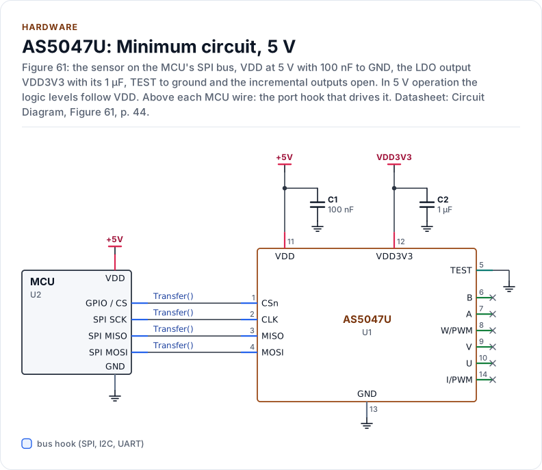
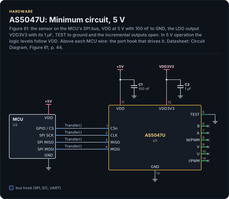
Figure description and sources
A schematic. The MCU is on the left, each of its pins level with the chip pin it connects to; above each wire is the hook of the driver's port that drives or reads it. Supply pins point up to their supply and decoupling, ground pins down. Pins on the right carry the loads and the pins tied to a supply or ground; a cross marks a pin left open. A dot is a junction; wires that cross without a dot are not connected.
Drawn from: docs/hardware.yml; inc/as5047u_spi_interface.hpp.
Hardware description: docs/hardware.yml
Drawn from:
AS5047U pinout, TSSOP-14
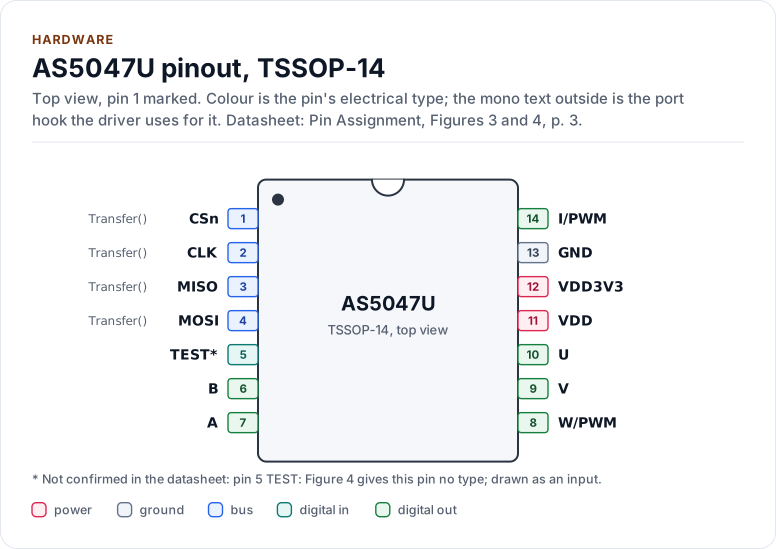
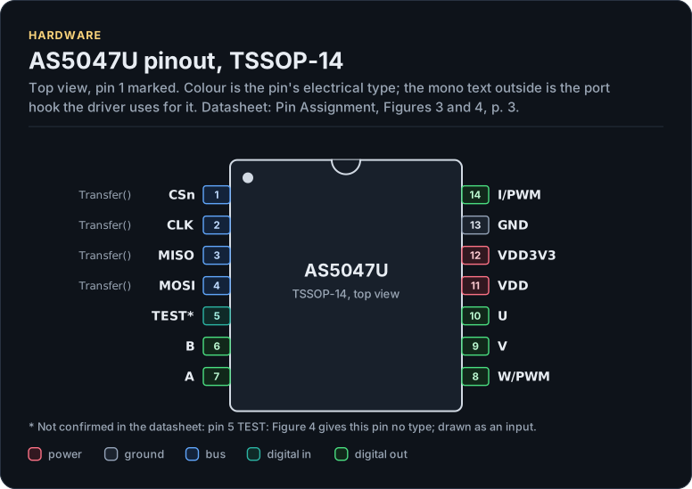
Figure description and sources
The AS5047U seen from the top, in its TSSOP-14 package. Pin 1 is marked by the dot; the numbers run counter-clockwise from it. Each pad is coloured by the pin's electrical type (legend below). Next to it is the pin's name and, in mono, the hook of the driver's port that drives or reads it; a pin without a hook is not used by the driver.
Drawn from: docs/hardware.yml; inc/as5047u_spi_interface.hpp.
Hardware description: docs/hardware.yml
Drawn from:
The layers, one of them yours
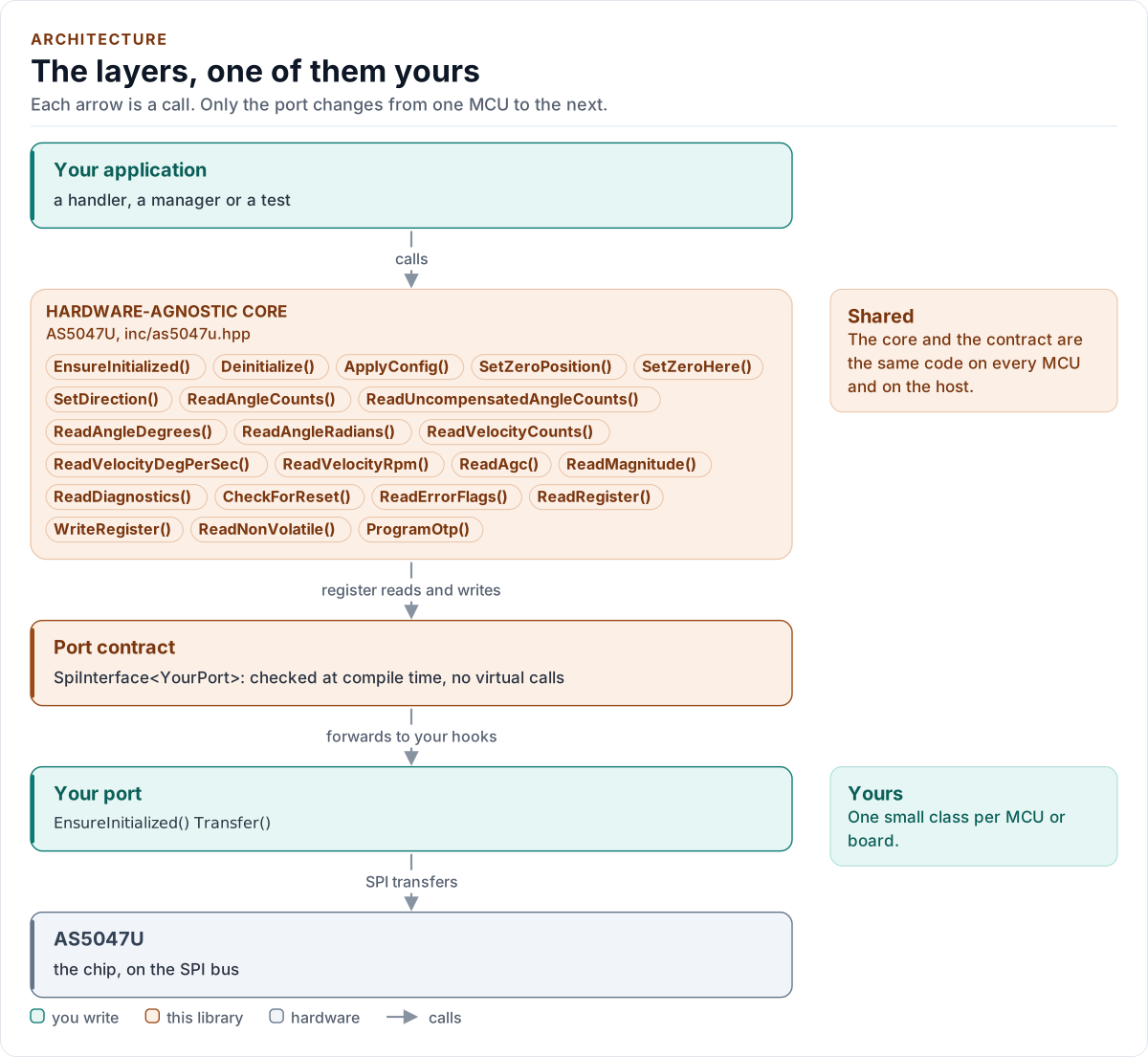
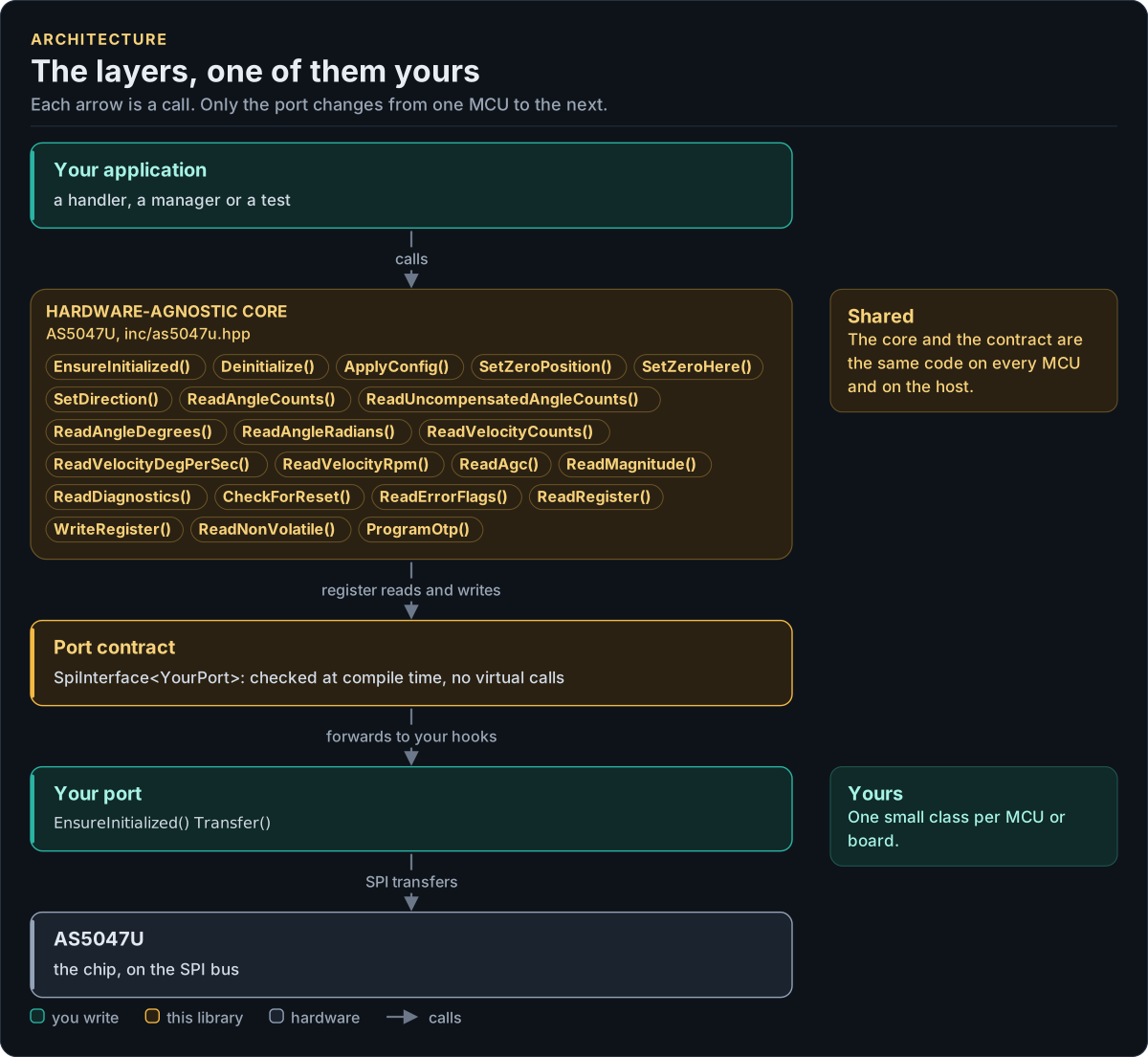
Figure description and sources
Top to bottom, each arrow is a call. Your application calls one object, whose public calls are listed from the umbrella header in inc/. The core turns each call into register reads and writes and hands them to the port contract (the CRTP base in inc/*_interface.hpp), which forwards them, at compile time, to the hooks of the port class you write; your port moves the bytes on the bus. The notes on the right say which layers stay the same on every MCU and which one you write. A library without a port contract has only the first two layers.
Drawn from: inc/as5047u.hpp public calls; inc/as5047u_spi_interface.hpp SpiInterface; figure module docs/diagrams/figures/driver-layers.py.
Figure module: docs/diagrams/figures/driver-layers.py
Drawn from:
public callsininc/as5047u.hppSpiInterfaceininc/as5047u_spi_interface.hpp
ProgramOtp(), step by step
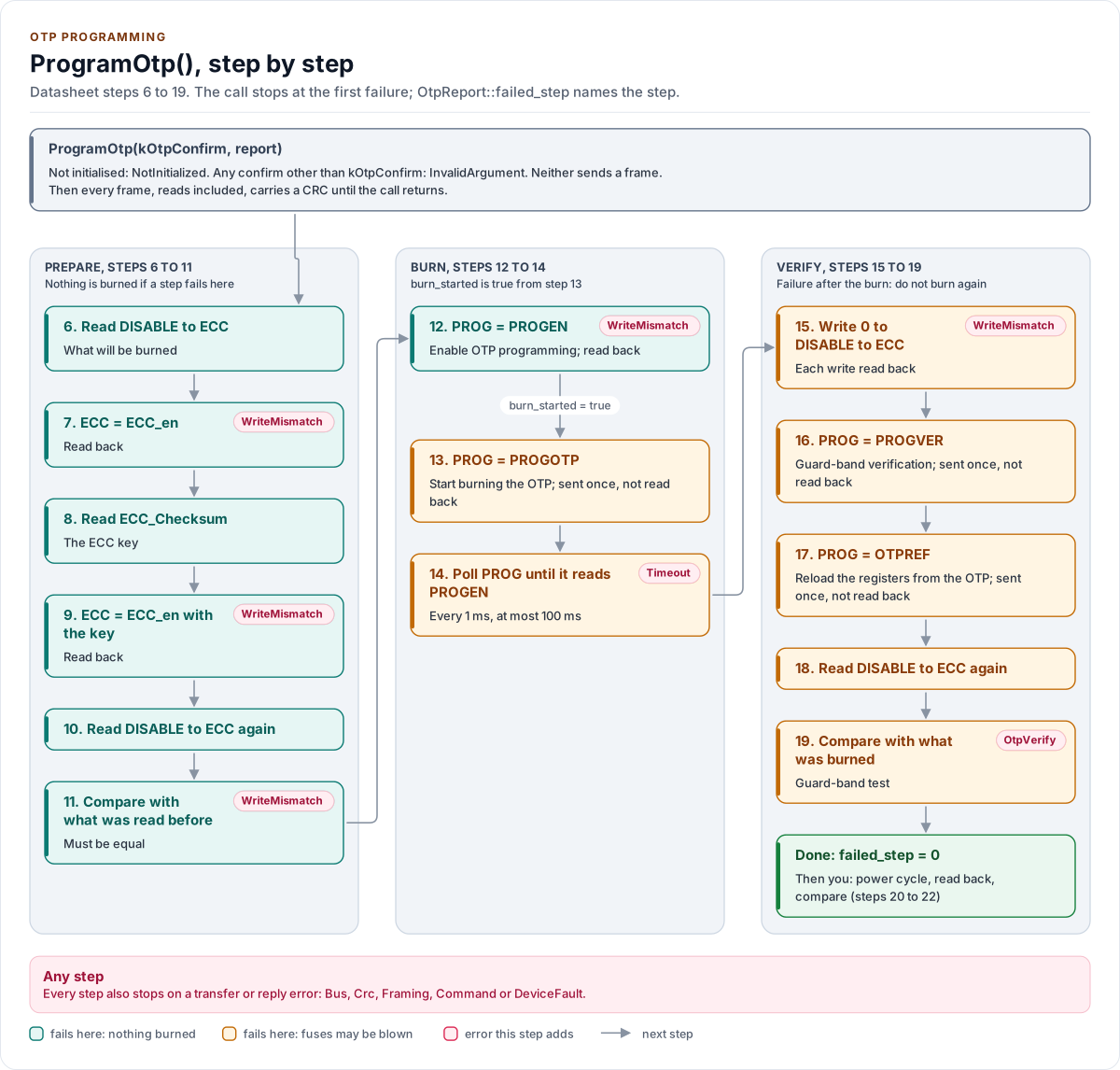
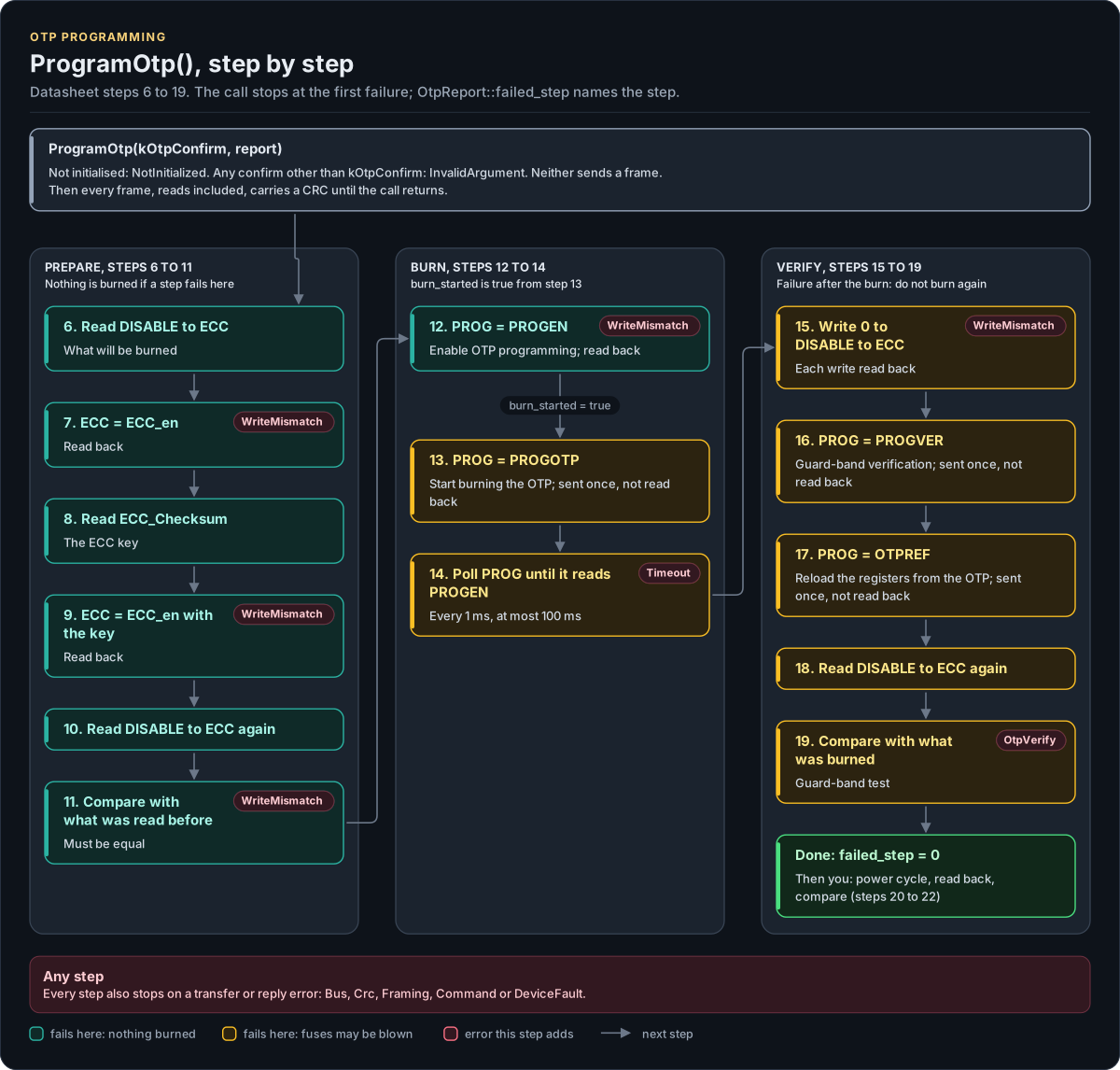
Figure description and sources
The call first refuses to run when the driver is not initialised or the confirm value is wrong, and sends nothing then. It switches every frame to a CRC-protected format and runs three phases, top to bottom and left to right: prepare (steps 6 to 11: read the settings, compute and write the ECC key, read everything back and compare), burn (steps 12 to 14: enable programming, start the burn, poll PROG every millisecond until the burn is done or the timeout passes) and verify (steps 15 to 19: clear the volatile copy, reload it from the OTP at the guard-band level and compare it with what was burned). A pill on a step names the error that step adds; any step also fails on a transfer or reply error. The call stops at the first failure and OtpReport::failed_step names the step. OtpReport::burn_started becomes true just before the step 13 frame is sent, so from there on the fuses may be blown even if the call fails. The steps, registers, timeout and errors are read from otpPrepare(), otpBurn() and otpVerify() in src/as5047u.ipp.
Drawn from: src/as5047u.ipp ProgramOtp; src/as5047u.ipp otpPrepare; src/as5047u.ipp otpBurn; src/as5047u.ipp otpVerify; inc/as5047u_types.hpp kOtpBurnTimeoutMs; inc/as5047u_registers.hpp PROG and ECC; figure module docs/diagrams/figures/otp-flow.py.
Figure module: docs/diagrams/figures/otp-flow.py
Drawn from:
ProgramOtpinsrc/as5047u.ippotpPrepareinsrc/as5047u.ippotpBurninsrc/as5047u.ippotpVerifyinsrc/as5047u.ippkOtpBurnTimeoutMsininc/as5047u_types.hppPROG and ECCininc/as5047u_registers.hpp
Every access is two frames
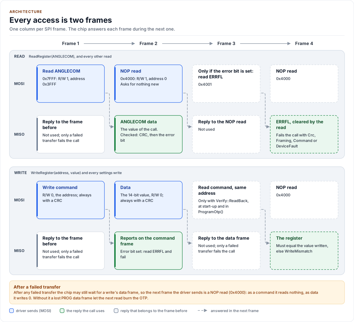
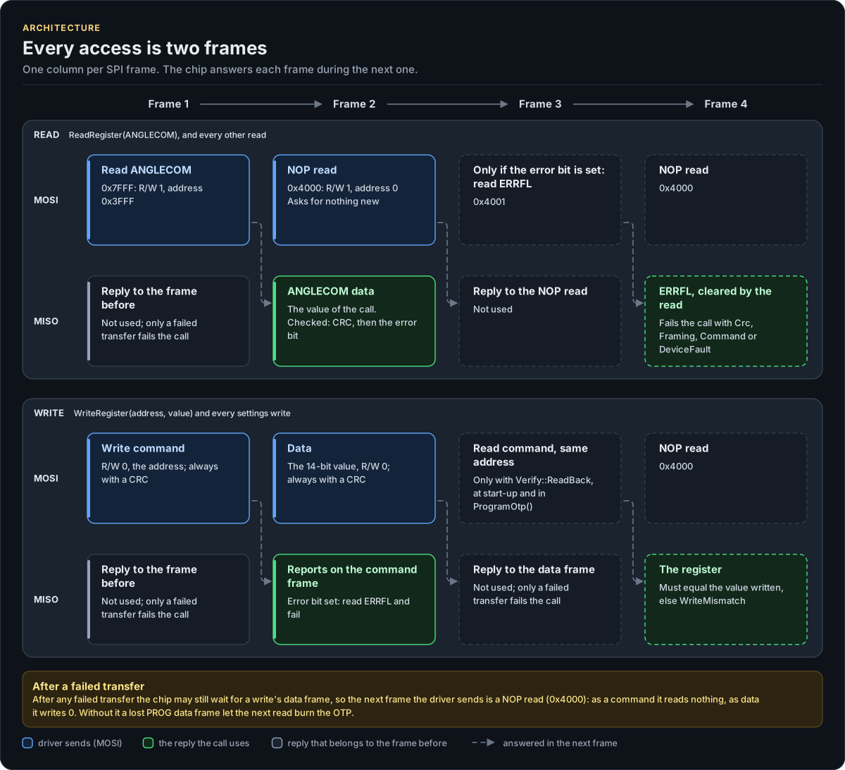
Figure description and sources
Time runs left to right, one column per SPI frame; the top row is what the driver sends on MOSI and the bottom row what the chip returns on MISO in the same frame. The chip answers a frame during the next one (dashed arrows), so a read sends the read command and then a NOP read, whose reply carries the register. The reply in the first frame belongs to the frame before it, so the driver fails the call there only when the transfer itself fails. When the reply that answers the call has its error bit set, the driver reads ERRFL (two more frames, dashed) to find out why and fails the call. A write sends the command frame (R/W at 0, the address) and the data frame, always with a CRC; the reply in the data frame reports on the command frame. The read-back after it (two more frames, dashed) is chosen per call with Verify::ReadBack; EnsureInitialized() and ProgramOtp() always read back. The frame words come from readRaw(), writeRaw() and resolveFlags() in src/as5047u.ipp. A note at the bottom gives the rule of FrameBus::Exchange(): after a failed transfer the next frame is a NOP read, so a lost data frame cannot turn the next command into data.
Drawn from: src/as5047u.ipp readRaw; src/as5047u.ipp writeRaw; src/as5047u.ipp resolveFlags; inc/as5047u.hpp detail::ClassifyErrorFlags; inc/as5047u_registers.hpp frame bits; inc/as5047u_spi_interface.hpp FrameBus::Exchange; figure module docs/diagrams/figures/read-pipeline.py.
Figure module: docs/diagrams/figures/read-pipeline.py
Drawn from:
readRawinsrc/as5047u.ippwriteRawinsrc/as5047u.ippresolveFlagsinsrc/as5047u.ippdetail::ClassifyErrorFlagsininc/as5047u.hppframe bitsininc/as5047u_registers.hppFrameBus::Exchangeininc/as5047u_spi_interface.hpp
SPI frames, bit by bit
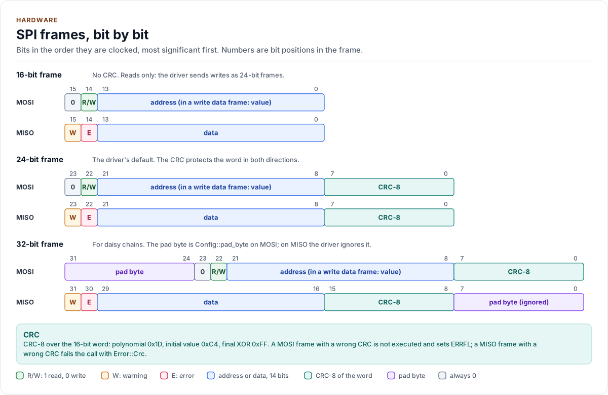
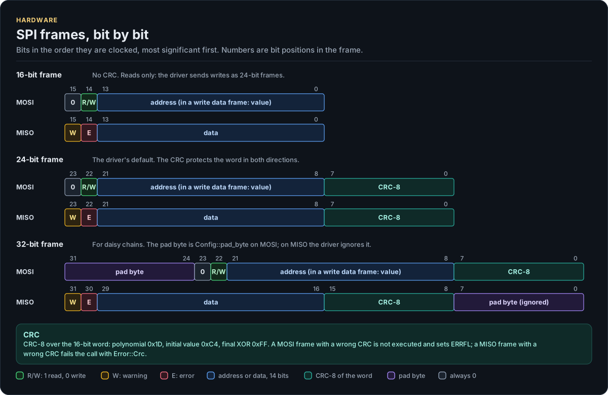
Figure description and sources
Each frame is drawn in the order it is clocked, most significant bit first, and the numbers above a row are bit positions in that frame. On MOSI the 16-bit command word holds the R/W bit (1 to read, 0 to write) and a 14-bit address; the data frame of a write has the same layout with R/W at 0 and the 14-bit value in place of the address. On MISO the reply word holds the warning bit, the error bit (a flag is set in ERRFL) and 14 data bits. The 24-bit frame adds the CRC-8 of the word in both directions. The 32-bit frame adds the pad byte: first on MOSI (the driver sends Config::pad_byte), last on MISO (the driver ignores it). The bit positions come from the frame constants in inc/as5047u_registers.hpp and the byte order from detail::FrameBus::Exchange in inc/as5047u_spi_interface.hpp. With 16-bit frames the driver sends writes as 24-bit frames.
Drawn from: inc/as5047u_registers.hpp frame bits; inc/as5047u_spi_interface.hpp detail::FrameBus::Exchange; inc/as5047u_spi_interface.hpp Crc8; inc/as5047u.hpp writeFormat; figure module docs/diagrams/figures/spi-frames.py.
Figure module: docs/diagrams/figures/spi-frames.py
Drawn from:
frame bitsininc/as5047u_registers.hppdetail::FrameBus::Exchangeininc/as5047u_spi_interface.hppCrc8ininc/as5047u_spi_interface.hppwriteFormatininc/as5047u.hpp