Architecture
How the driver is built: three layers, one of them yours, how one call travels through them, and how every SPI reply is checked before it is used.
Datasheet sections this page relies on
From Infineon IFX-ntz1491827137291 1.2:
- Reset State, Config Mode, Mission Mode and Critical Fault: 4.3.1 TDS_IC Operation states; Figure 4, p. 19
- Feedback freeze and update: 4.10.5 TDS_Update/Freeze Mechanism; Figure 22, p. 43
- SPI frame, mode and CRC-8 SAE J1850: 5.1.1 TDS_General information; 5.1.2 TDS_Cyclic redundancy check (CRC), p. 47
- The reply pipeline, frames and reply status: 5.2.1 TDS_Data flow; 5.2.3 SPI frame definition, p. 50
- Central registers, reset values and bit types: 5.3.1 Overview of Register Types; 5.3.2 Central registers, p. 54
- FB_STAT, the status summary: 5.3.2.21 Feedback Status Register, p. 77
- Channel registers and their bank addresses: 5.3.3 Channel registers, Tables 24 and 25, p. 85
All of them, with the driver API for each: Datasheet map.
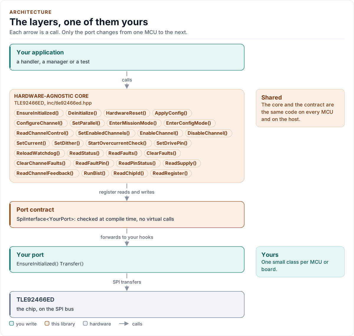
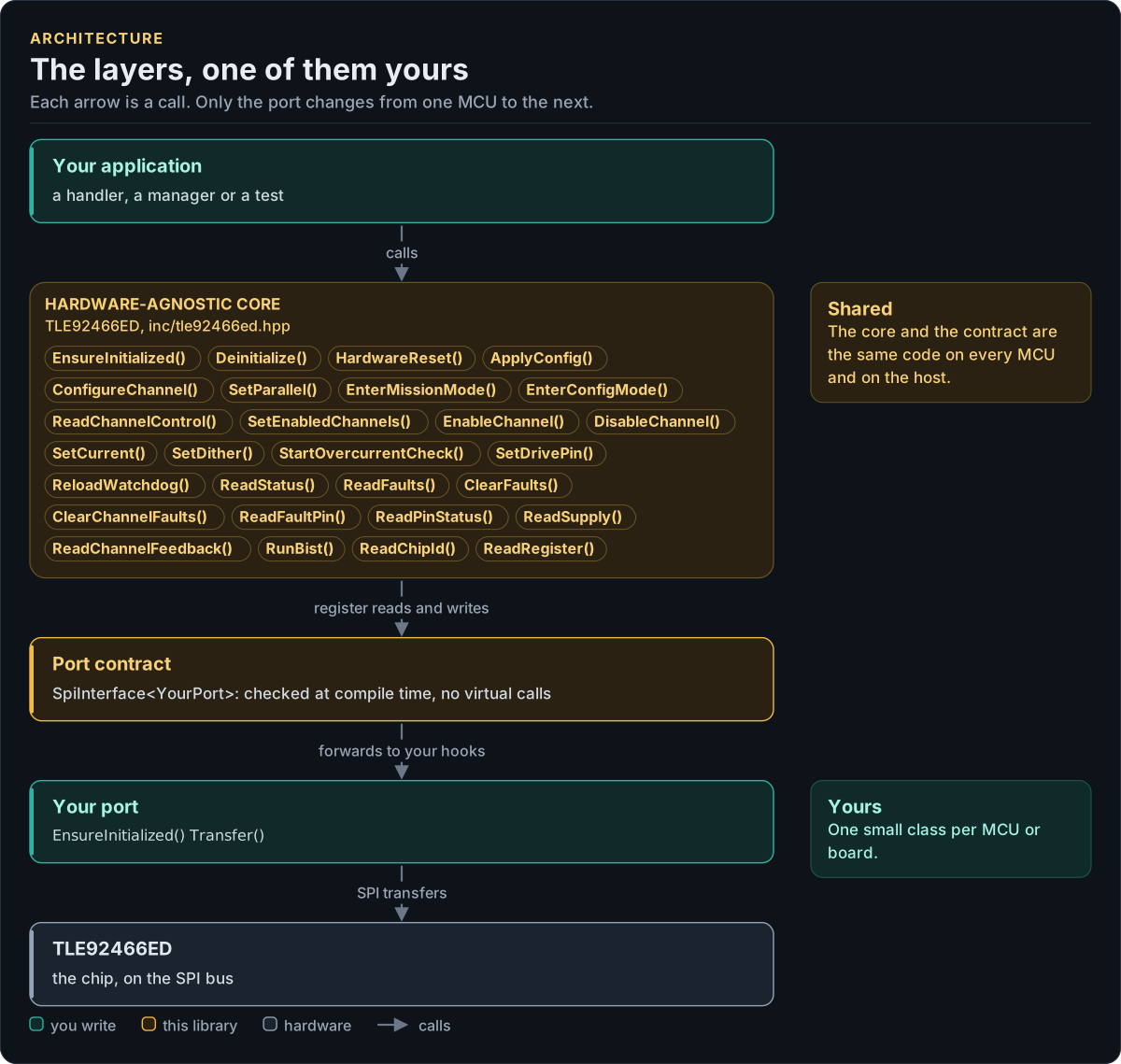
Figure description and sources
Top to bottom, each arrow is a call. Your application calls one object, whose public calls are listed from the umbrella header in inc/. The core turns each call into register reads and writes and hands them to the port contract (the CRTP base in inc/*_interface.hpp), which forwards them, at compile time, to the hooks of the port class you write; your port moves the bytes on the bus. The notes on the right say which layers stay the same on every MCU and which one you write. A library without a port contract has only the first two layers.
Drawn from: inc/tle92466ed.hpp public calls; inc/tle92466ed_spi_interface.hpp SpiInterface; figure module docs/diagrams/figures/driver-layers.py.
Layers
| Layer | Files | Owns |
|---|---|---|
| Core | inc/tle92466ed.hpp, src/tle92466ed.ipp |
Start-up, operation states, channels, feedback, diagnosis, the driver's copies and latch |
| Types and registers | inc/tle92466ed_types.hpp, inc/tle92466ed_registers.hpp |
Error, Result<T>, Config and Validate(), decoded values, conversions; the register map and CRC |
| Port contract | inc/tle92466ed_spi_interface.hpp |
The CRTP base, CtrlPin and GpioSignal, the SpiPort concept, the bus requirements, the frame codec and the pipeline (detail::Transport) |
| Platform port | Your class | Bus bring-up and 32-bit frames, delays, optionally the control pins and logging |
| Kconfig layer | inc/tle92466ed_kconfig.hpp |
Optional: a Config from ESP-IDF menuconfig |
One call through the layers
sequenceDiagram
    participant App as Your code
    participant Core as TLE92466ED<Port>
    participant Bus as detail::Transport
    participant Port as Your port
    App->>Core: SetCurrent(Ch0, 400000)
    Note over Core: range check, TARGET = 6553
    Core->>Bus: Access(write SETPOINT of CH0)
    Bus->>Port: Transfer(write frame)
    Port-->>Bus: reply to the previous anchor
    Note over Bus: anchor check: CRC, width, ICVID or FB_STAT
    Bus->>Port: Transfer(anchor read of FB_STAT)
    Port-->>Bus: reply to the write
    Note over Bus: CRC, 16-bit, status 0, R/W echo 1
    Bus-->>Core: Ok
    Note over Core: copy updated after the chip took it
    Core-->>App: Result<uint32_t>{399976, Ok}
The SPI pipeline
The chip answers each frame during the next one (section 5.2.1), and a reply carries no address, so the driver completes every access inside one call, in two frames: the request, then an anchor read whose reply arrives with the next access. The anchor differs in width from the request's reply: FB_STAT (22 bits) after a write or a 16-bit read, ICVID (16 bits) after a 22-bit read. A request the chip never took then leaves the previous anchor's reply in its slot, and that reply fails the width check instead of passing as data.
Every word read is checked in this order before anything decodes it (detail::DecodeReply()):
| Check | Section | On failure |
|---|---|---|
| All zeros, all ones, or the frame just sent (a looped-back MOSI) | KB-CPP-116 | NoDevice |
| Reply mode 10B: the critical fault frame (bits 31..24 are don't care, so no CRC), confirmed by one more frame | 5.2.3.5 | CriticalFault, flags kept, EN low; a single one is ReplyMismatch |
| CRC-8 SAE J1850 of bits 23..0 | 5.1.2 | Crc |
| Reply mode 11B (reserved) or the wrong width for the request | 5.2.3.3, 5.2.3.4 | ReplyMismatch |
| Status of a 16-bit reply: CRC error, frame error, read-only write, internal bus fault | 5.2.3.3 | Crc, FrameRejected, DeviceFault |
| The R/W echo of a 16-bit reply | 5.2.3.3 | ReplyMismatch |
| The same word in both slots (the chip ignored the request and repeated its last reply) | 5.1.1 | ReplyMismatch |
| The previous anchor: ICVID manufacturer 0xC1; FB_STAT without POR_event or RES_event | 5.3.2.19, 4.1.1 | ReplyMismatch, UnexpectedReset |
After any failure the next access first sends one anchor frame alone and discards its reply, so the pipeline is in
a known state again (KB-CPP-118). A read whose reply failed a check is repeated up to Config::max_retries times,
except DIAG_WARN_CHGR, which a read changes (4.9.3); a port failure, a confirmed critical fault frame and a
detected reset are not. A write is never repeated: its outcome is
unknown, and Verify::ReadBack is the way to settle it. GetBusDiagnostics() counts frames, retries, rejected
replies and resyncs.
State the driver keeps
| Copy | Updated | Why |
|---|---|---|
CH_CTRL (IsMissionMode(), GetEnabledChannels()) |
From a read of CH_CTRL before every enable change and after EnterMissionMode(), and after the chip took a write |
The chip clears EN_CH and OP_MODE on its own; a write is the register as read with only what the call names changed (KB-CPP-121, -122) |
TARGET per channel (GetCurrentSetpoint()) |
After the chip took the write | The programmed value, with the pair's scale |
The fault latch (GetLatchedFaults()) |
Every read of a diagnosis register | Clear-on-read and clear-on-write flags are never lost to an internal read (KB-CPP-119) |
The start-up faults (GetStartupFaults()) |
Each start | What the chip held before the driver cleared it |
The configuration (GetConfig()) |
After the chip took it | Conversions use the chip's actual settings (KB-CPP-128) |
Feedback
ReadChannelFeedback() follows the readout of Figure 22 (section 4.10.5): FB_UPD shows new values; FB_FRZ freezes
the channel's feedback registers so FB_DC, FB_VBAT, FB_I_AVG, FB_IMIN_IMAX and FB_PERIOD_MIN_MAX come from one
measurement period; releasing the freeze clears the FB_UPD bit. A TP_MANT of 0 (no measurement period, for example
a dither clock of 0, section 4.4.2) is NotReady, never a current of 0 (KB-CPP-127).
Design choices
- CRTP, not virtual functions. The port is a template parameter constrained by the
SpiPortconcept, so every call is resolved at compile time and a missing hook is a compile error that names it. - Optional hooks by named concepts.
GpioSet,GpioReadandLogare detected bydetail::Has*concepts; a hook declared with another signature is a compile error, never ignored.DelayUsis required. - No I/O in the constructor. Construction cannot fail, so the driver can be a static or a member of a handler.
- One error type.
Result<T>carries a value and anError; nothing throws and nothing returns a barebool. - No heap, no exceptions, no RTTI, no
std::function, noprintf. The driver is a header-only template with no mutable static state; the frame buffers belong to the driver object.
Source map
| You want | Read |
|---|---|
| The public API | inc/tle92466ed.hpp |
| How a call is implemented | src/tle92466ed.ipp |
| Register addresses, bits and the CRC | inc/tle92466ed_registers.hpp |
| The port contract, the frames and the pipeline | inc/tle92466ed_spi_interface.hpp |
Next: Contract.