Figures
Every figure on this site is drawn by a Python module from facts extracted from the code, so it is rebuilt,
not redrawn, when the code changes. CI runs kokeb-docs figures --check and fails when a
committed figure no longer matches the code. Each figure below lists the files it is drawn from.
Inside the PCAL9555A
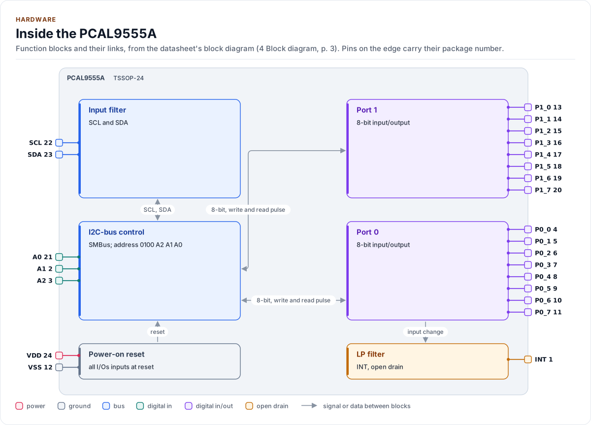
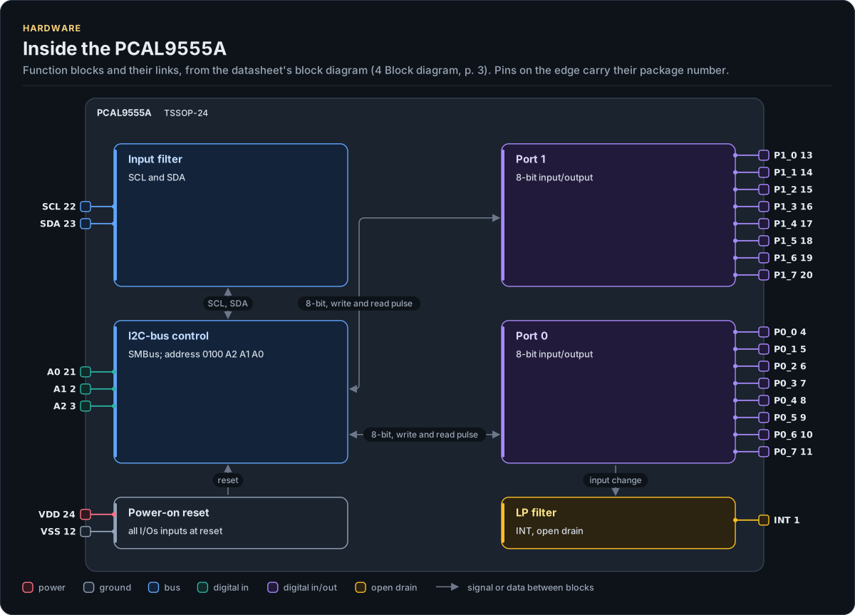
Figure description and sources
The PCAL9555A's function blocks inside its outline. Arrows between blocks carry signals or data in the direction they point (both ways where they have two heads). The package pins stand on the left and right edges with their numbers, each wired to the block it reaches.
Drawn from: docs/hardware.yml; inc/pcal9555_i2c_interface.hpp.
Hardware description: docs/hardware.yml
Drawn from:
PCAL9555A: Typical application
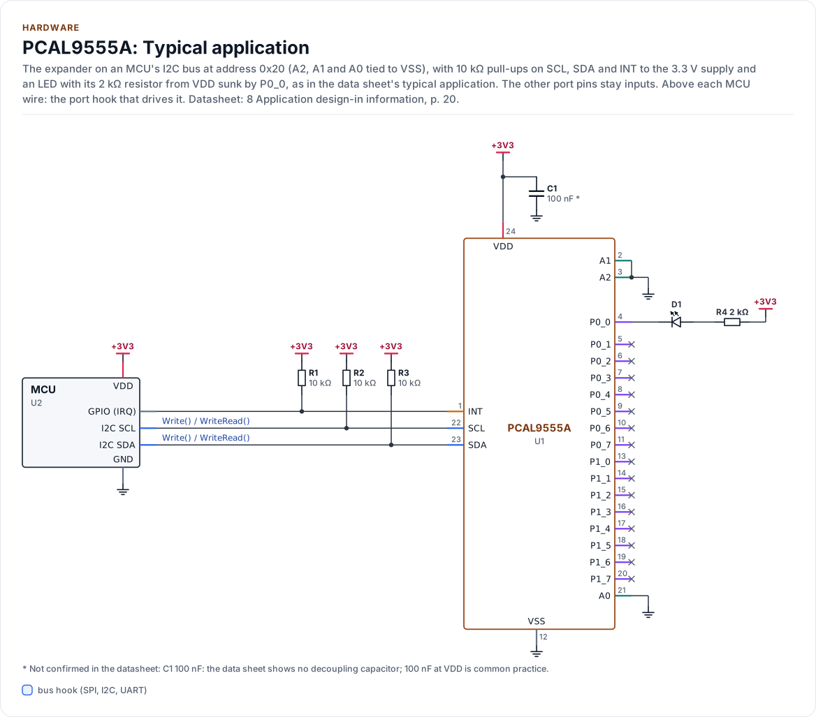
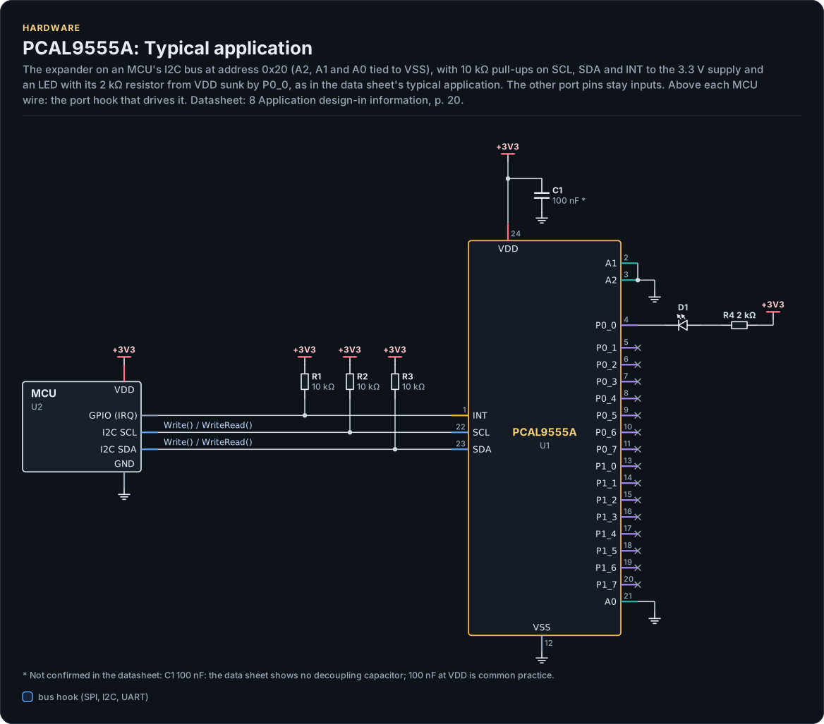
Figure description and sources
A schematic. The MCU is on the left, each of its pins level with the chip pin it connects to; above each wire is the hook of the driver's port that drives or reads it. Supply pins point up to their supply and decoupling, ground pins down. Pins on the right carry the loads and the pins tied to a supply or ground; a cross marks a pin left open. A dot is a junction; wires that cross without a dot are not connected.
Drawn from: docs/hardware.yml; inc/pcal9555_i2c_interface.hpp.
Hardware description: docs/hardware.yml
Drawn from:
PCAL9555A pinout, TSSOP-24
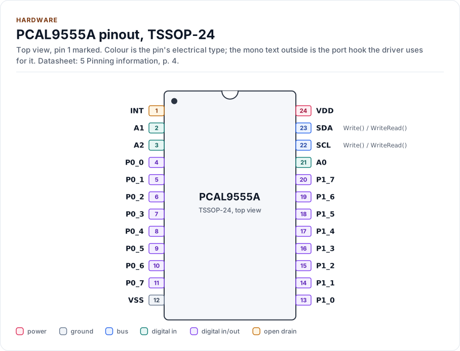
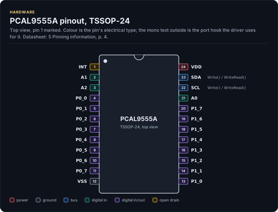
Figure description and sources
The PCAL9555A seen from the top, in its TSSOP-24 package. Pin 1 is marked by the dot; the numbers run counter-clockwise from it. Each pad is coloured by the pin's electrical type (legend below). Next to it is the pin's name and, in mono, the hook of the driver's port that drives or reads it; a pin without a hook is not used by the driver.
Drawn from: docs/hardware.yml; inc/pcal9555_i2c_interface.hpp.
Hardware description: docs/hardware.yml
Drawn from:
The layers, one of them yours
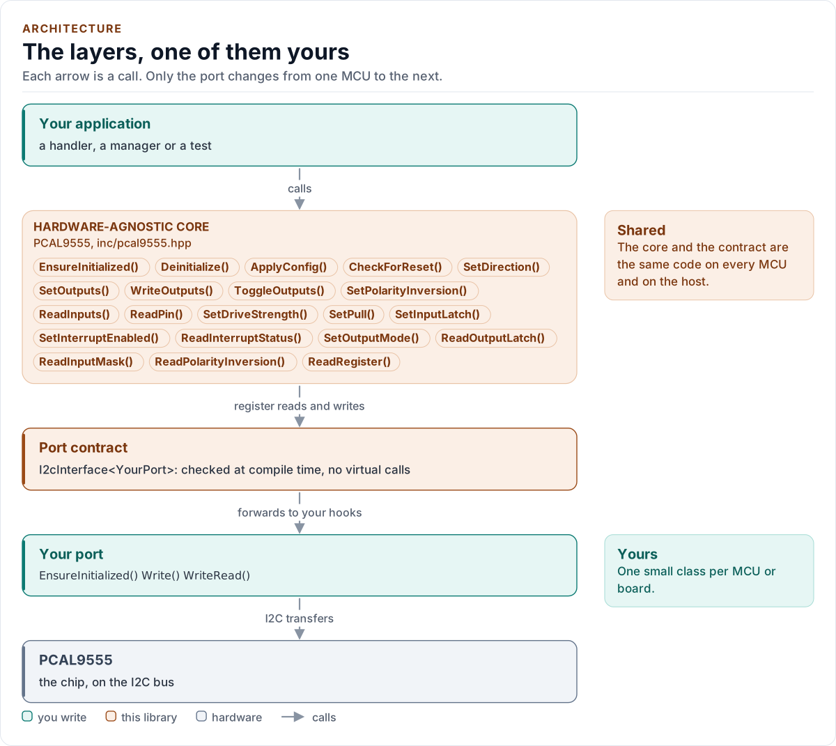
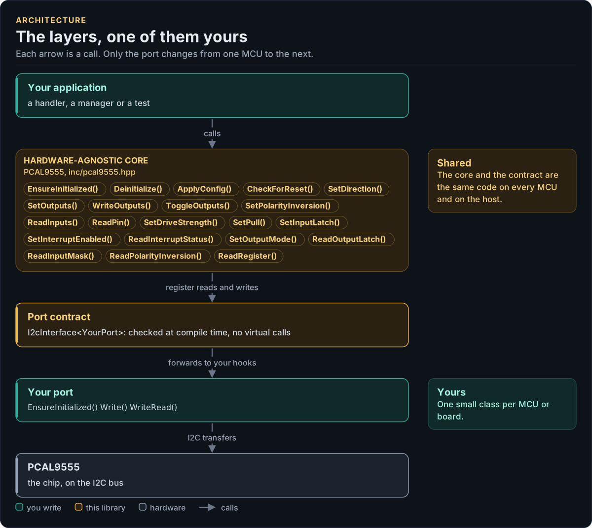
Figure description and sources
Top to bottom, each arrow is a call. Your application calls one object, whose public calls are listed from the umbrella header in inc/. The core turns each call into register reads and writes and hands them to the port contract (the CRTP base in inc/*_interface.hpp), which forwards them, at compile time, to the hooks of the port class you write; your port moves the bytes on the bus. The notes on the right say which layers stay the same on every MCU and which one you write. A library without a port contract has only the first two layers.
Drawn from: inc/pcal9555.hpp public calls; inc/pcal9555_i2c_interface.hpp I2cInterface; figure module docs/diagrams/figures/driver-layers.py.
Figure module: docs/diagrams/figures/driver-layers.py
Drawn from:
public callsininc/pcal9555.hppI2cInterfaceininc/pcal9555_i2c_interface.hpp
One pin call, and what each outcome leaves
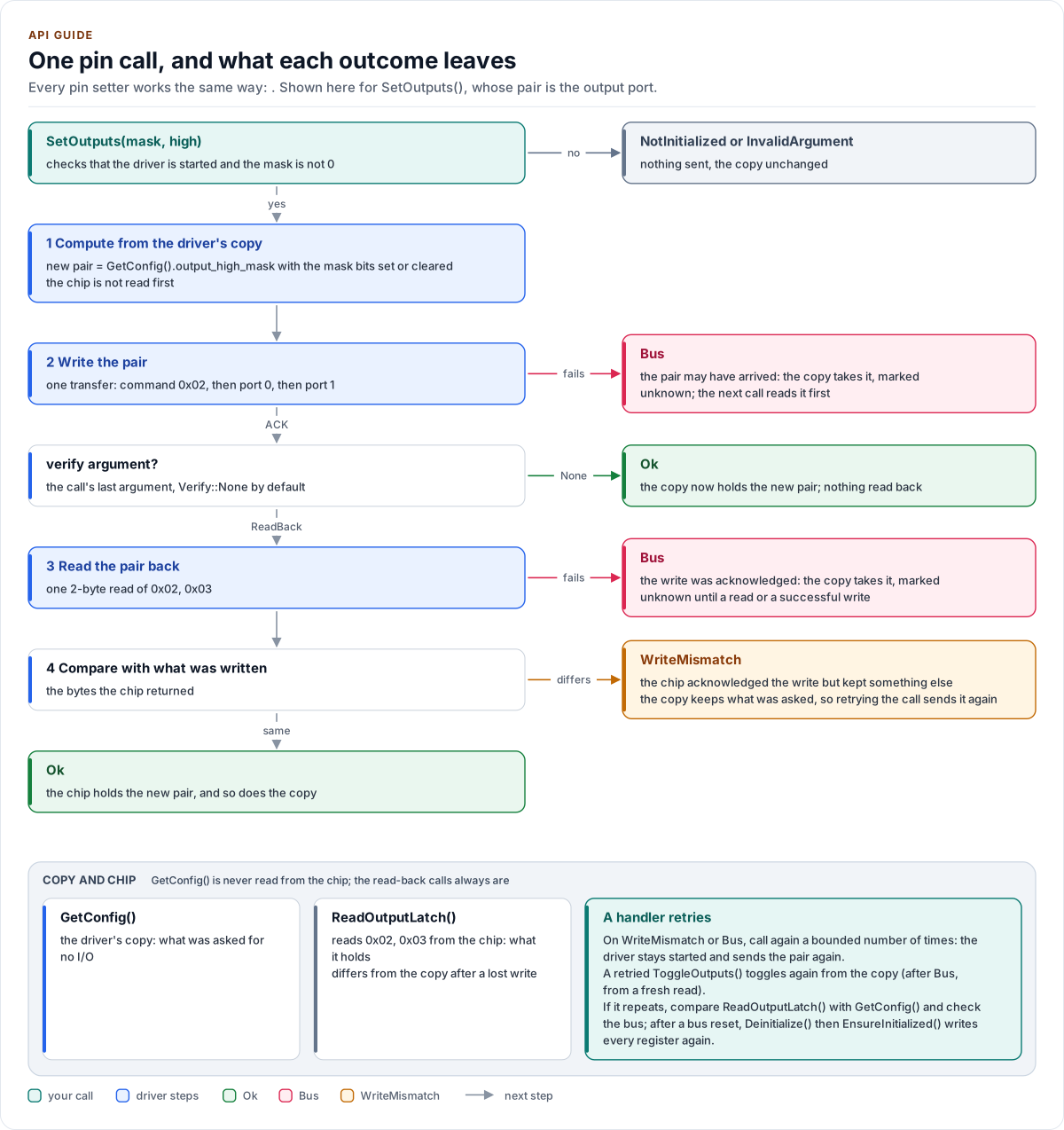
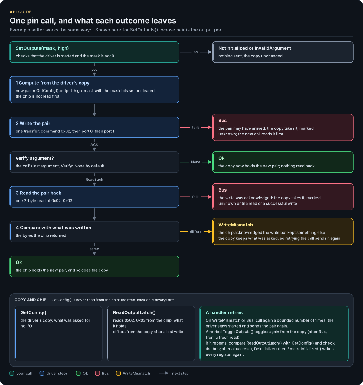
Figure description and sources
Top to bottom on the left, the steps of SetOutputs(); the other pin setters take the same path to their own register pair. The call first checks that the driver is started and the mask is not 0, with no I/O. It computes the new output pair from the driver's copy (GetConfig()) without reading the chip, and writes it in one transfer. With Verify::ReadBack passed (the default is Verify::None) it reads the pair back. The cards on the right are the outcomes: Bus may have delivered the pair, so the copy takes the written level, marked unknown, and the next call reads it before building on it; WriteMismatch means the chip acknowledged the write but holds something else, and the copy keeps what was asked, so retrying the call sends it again; Ok updates the copy. The band at the bottom contrasts the copy with ReadOutputLatch(), which reads the output pair from the chip, and says how a handler retries.
Drawn from: src/pcal9555.ipp SetOutputs, writeMask, storeMask, writePairChecked, ReadOutputLatch; inc/pcal9555_types.hpp Verify; inc/pcal9555_registers.hpp kOutputPort0; figure module docs/diagrams/figures/pin-write.py.
Figure module: docs/diagrams/figures/pin-write.py
Drawn from:
SetOutputs, writeMask, storeMask, writePairChecked, ReadOutputLatchinsrc/pcal9555.ippVerifyininc/pcal9555_types.hppkOutputPort0ininc/pcal9555_registers.hpp
The register map
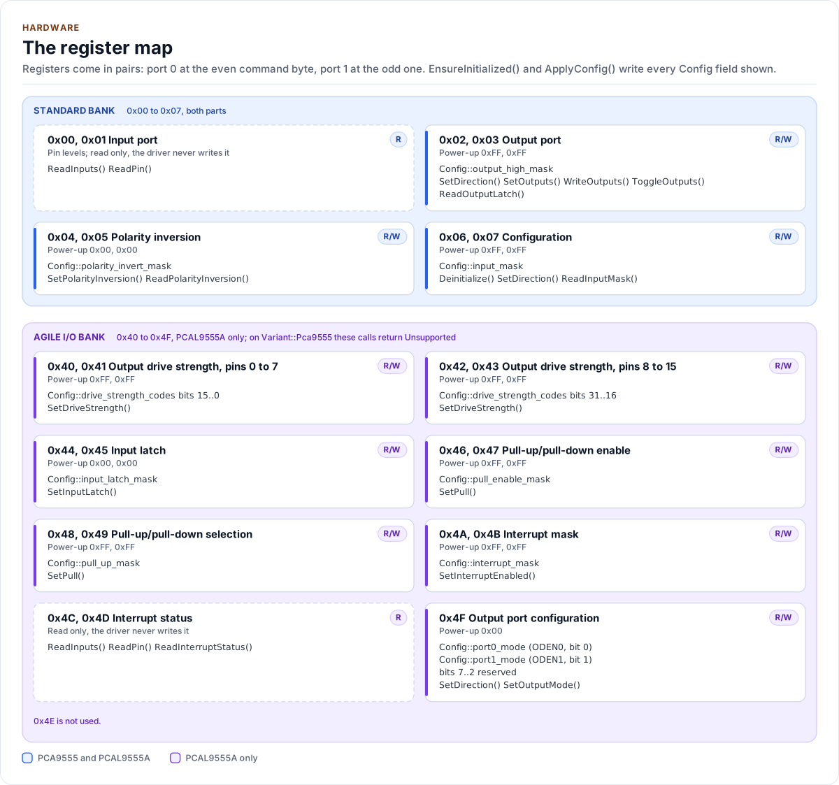
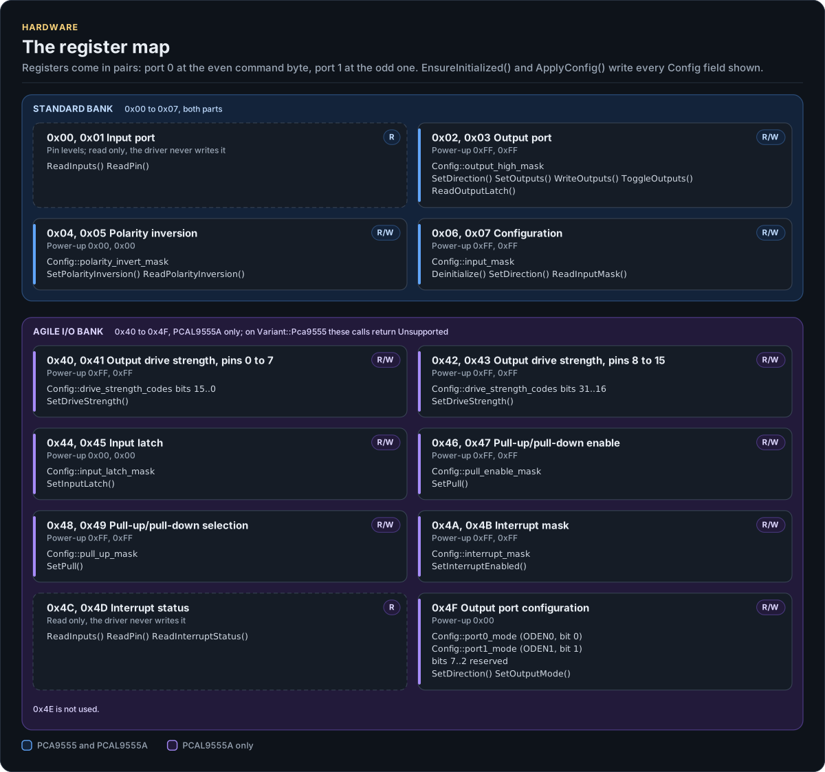
Figure description and sources
One card per register pair, in command-byte order; port 0 is the even byte, port 1 the odd one. The top band is the standard bank, 0x00 to 0x07, on both the PCA9555 and the PCAL9555A; the lower band is the Agile I/O bank, 0x40 to 0x4F, which only the PCAL9555A has. Each card gives the access (R or R/W), the power-up value of each register, the Config field the driver keeps for it, and the calls that read or write it. EnsureInitialized() and ApplyConfig() write every Config field shown. The input ports and the interrupt status are read only, so they have no Config field. Addresses come from the constants in inc/pcal9555_registers.hpp, fields from the pair lists in inc/pcal9555.hpp and calls from src/pcal9555.ipp.
Drawn from: inc/pcal9555_registers.hpp register constants; inc/pcal9555.hpp StandardPairs, AgilePairs, OutputPortConfig; src/pcal9555.ipp calls; figure module docs/diagrams/figures/register-map.py.
Figure module: docs/diagrams/figures/register-map.py
Drawn from:
register constantsininc/pcal9555_registers.hppStandardPairs, AgilePairs, OutputPortConfigininc/pcal9555.hppcallsinsrc/pcal9555.ipp
What EnsureInitialized() does
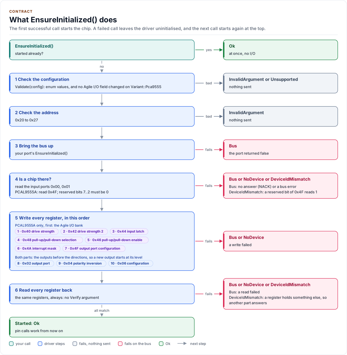
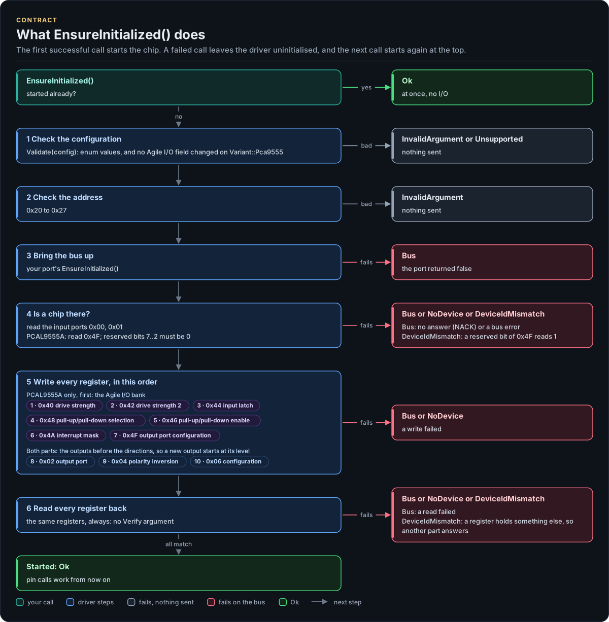
Figure description and sources
Top to bottom on the left, the steps of the first EnsureInitialized() call; once it has succeeded, the call returns Ok at once with no I/O. The configuration and the address are checked before any I/O. Then the port brings the bus up, and the presence check reads the input ports; on a PCAL9555A it also reads 0x4F, whose reserved bits must be 0. Every register the driver owns is then written, in the order the code uses: on a PCAL9555A the Agile I/O bank first and 0x4F after it, then the output values before the directions, so a new output starts at its configured level. Every register is read back, unconditionally; a register that does not hold what was written means another part answers. Each card on the right is the error a step returns. After any failure the driver stays uninitialised and the next call starts again at the top.
Drawn from: src/pcal9555.ipp EnsureInitialized, initialize, checkPresence, writeAll, verifyAll; inc/pcal9555.hpp StandardPairs, AgilePairs; inc/pcal9555_types.hpp Validate, kMinI2cAddress, kMaxI2cAddress; inc/pcal9555_registers.hpp register constants; figure module docs/diagrams/figures/start-up.py.
Figure module: docs/diagrams/figures/start-up.py
Drawn from:
EnsureInitialized, initialize, checkPresence, writeAll, verifyAllinsrc/pcal9555.ippStandardPairs, AgilePairsininc/pcal9555.hppValidate, kMinI2cAddress, kMaxI2cAddressininc/pcal9555_types.hppregister constantsininc/pcal9555_registers.hpp