Transfer function
How a voltage at VOUT becomes a temperature: the datasheet's equation, the integer arithmetic the driver uses, the numbers at the ends of each range and what limits the accuracy of the result.
Datasheet sections this page relies on
From Microchip Technology Inc. DS20001942 L:
- Accuracy of each device: DC Electrical Characteristics, Sensor Accuracy, p. 3
- Transfer function: V0 and TC of each device: 4.0 Applications Information, Equation 4-1; DC Electrical Characteristics, p. 10
All of them, with the driver API for each: Datasheet map.
The equation
The sensor measures the die temperature with a diode and scales it to a voltage (Equation 4-1, p. 10):
VOUT = TC x TA + V0 °C
| Family | V0 at 0 °C | TC | Source |
|---|---|---|---|
| MCP9700, MCP9700A, MCP9700B | 500 mV | 10.0 mV/°C | DC Electrical Characteristics, p. 3 and p. 4 |
| MCP9701, MCP9701A | 400 mV | 19.5 mV/°C | the same tables |
The values are typical; the datasheet gives no minimum or maximum for either, only the accuracy of the result (below). The datasheet's note 3 on p. 3 points at "Equation 4-2" for the first-order equation, but Equation 4-2 is the self-heating equation: the transfer function is Equation 4-1. The driver follows Equation 4-1.
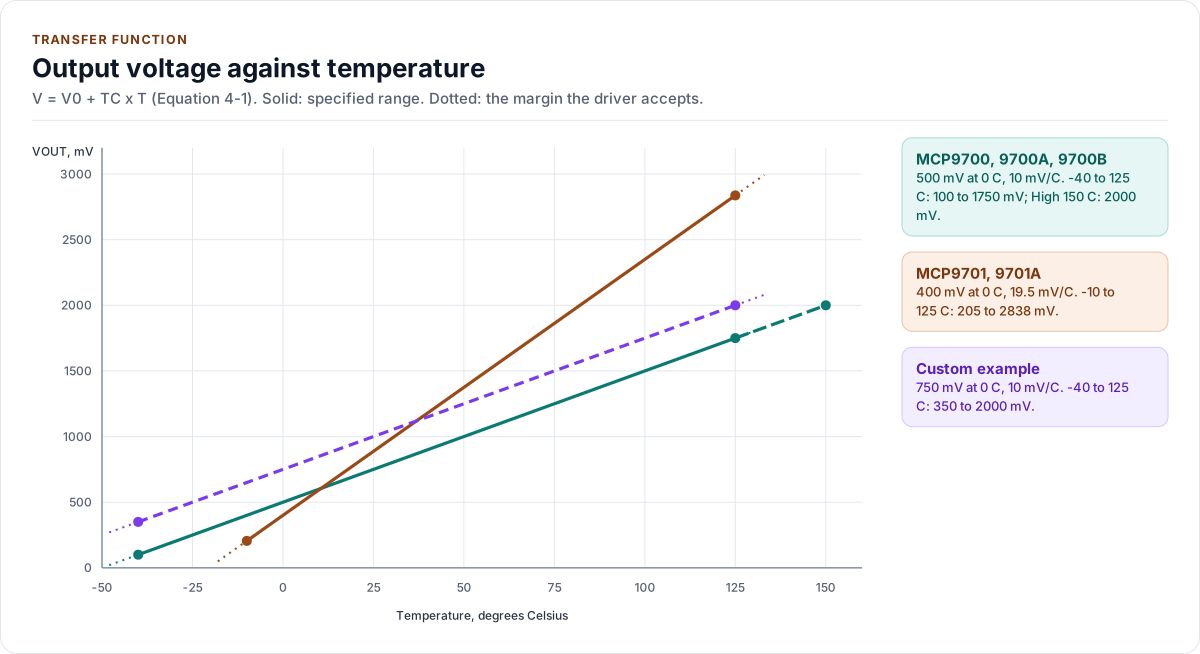
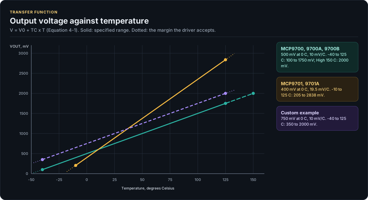
Figure description and sources
The horizontal axis is the die temperature, the vertical axis the voltage at VOUT, from Equation 4-1, V = V0 + TC x T. The MCP9700, MCP9700A and MCP9700B share the lower line (500 mV at 0 C, 10.0 mV/C); the MCP9701 and MCP9701A the steeper one (400 mV at 0 C, 19.5 mV/C). The dashed line is a Custom example from the Configuration page. Each line is solid over its specified temperature range and dotted over the plausibility margin the driver adds on each side (range_margin_mc, default 8 C): a reading outside the solid part and its dotted margin is OutputLow or OutputHigh, never a temperature. The dots mark the ends of the specified range and the voltage there.
Drawn from: inc/mcp9700_types.hpp kVariantTable; inc/mcp9700_types.hpp range_margin_mc; tests/docs/configuration.cpp custom-offset; figure module docs/diagrams/figures/transfer-function.py.
The arithmetic
The driver works in integers only: temperatures in milli-degrees (_mc), voltages in millivolts (_mv) and the
slope in microvolts per degree (_uv_per_c). Solving Equation 4-1 for the temperature, with the mean output V in
millivolts:
The mean, the divider and the equation are one integer expression with a single rounding at the end (half away from
zero), so averaging eight conversions never adds a rounding step. It is evaluated in 64 bits. The reverse,
MilliCToOutputMv(), rounds to the nearest millivolt and returns 0 for a temperature whose output would be negative.
| Temperature | MCP9700 family | MCP9701 family |
|---|---|---|
| -40 °C | 100 mV | (below range) |
| -10 °C | 400 mV | 205 mV |
| 0 °C | 500 mV | 400 mV |
| +25 °C | 750 mV | 887.5 mV |
| +85 °C | 1350 mV | 2057.5 mV |
| +125 °C | 1750 mV | 2837.5 mV |
| +150 °C (High) | 2000 mV | (no High option) |
Datasheet p. 9 gives the output ranges as 100 mV to 1.75 V (MCP9700 family) and 200 mV to 3 V (MCP9701 family); the second is rounded: 205 mV and 2837.5 mV are the exact ends of -10 °C and +125 °C.
The window of OutputLow and OutputHigh is the specified range plus range_margin_mc on each side (default 8 °C):
for an MCP9700 that is -48 °C to +133 °C, 20 mV to 1830 mV (2080 mV with the High option). The margin is the
datasheet's worst-case +6 °C error plus 2 °C of ADC error (open question A-4); see
Configuration.
ToCelsius() converts milli-degrees to a float for printing. It is the only floating-point in the driver; the
result of every call is an integer.
The error budget
The reading is the sensor's error plus the ADC's, and the driver reports the sum without correcting for either:
| Source | Size | Where it is described |
|---|---|---|
| Sensor accuracy | ±1 °C to ±4 °C by grade and span, at VDD = 3.3 V (MCP9700 family) or 5.0 V (MCP9701 family) | Hardware, AccuracyLimitsFor() |
| Nonlinearity | ±0.5 °C typical, 0 to +70 °C | not corrected; Limitations |
| Line regulation | 0.1 °C per volt away from the tested supply | not corrected; Limitations |
| Self-heating | 0.179 °C at the worst case, 25 °C | not corrected |
| ADC step | ResolutionMilliC(), 81 m°C for a 12-bit 3.3 V ADC on a 10 mV/°C part |
Hardware |
| ADC offset and gain | whatever your ADC has; calibrated millivolts remove most of it | your port |
| Noise | averaged away by samples; flagged by max_spread_mv |
Configuration |
When a part is off by a fixed amount, measure it once at a known temperature and set offset_cal_mc: a one-point
calibration at +25 °C improves the accuracy to about ±0.5 °C from 0 to +70 °C (section 4.1, p. 10), and the
datasheet notes that a relative change from the calibration point is accurate to the same degree. A calibration at
one point cannot fix the slope; a gain trim is not part of this version (Limitations).