Architecture
How the driver is built: the core, the port contract, and your port; and what one reading does.
Datasheet sections this page relies on
From Microchip Technology Inc. DS20001942 L:
- Output voltage range and an output outside it: 3.2 Output Voltage Pin (VOUT), p. 9
All of them, with the driver API for each: Datasheet map.
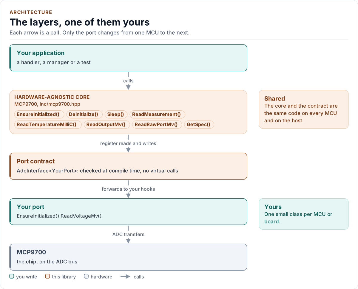
Figure description and sources
Top to bottom, each arrow is a call. Your application calls one object, whose public calls are listed from the umbrella header in inc/. The core turns each call into transfers (or, for an analog part, conversion requests) and hands them to the port contract (the CRTP base in inc/*_interface.hpp), which forwards them, at compile time, to the hooks of the port class you write; your port moves the bytes on the bus. The notes on the right say which layers stay the same on every MCU and which one you write. A library without a port contract has only the first two layers.
Drawn from: inc/mcp9700.hpp public calls; inc/mcp9700_adc_interface.hpp AdcInterface; figure module docs/diagrams/figures/driver-layers.py.
| Layer | Files | Owns |
|---|---|---|
| Core | inc/mcp9700.hpp, src/mcp9700.ipp |
Lifecycle, sampling, the clip, noise and range checks |
| Types | inc/mcp9700_types.hpp |
Error, Result<T>, Config, the variant table, the conversion functions, presets |
| Compile-time helpers | inc/mcp9700_detail.hpp |
Typed integer literals, exact hook probes, enumeration checks |
| Port contract | inc/mcp9700_adc_interface.hpp |
The CRTP base, CtrlPin, GpioSignal, the AdcPort concept, the output-load limits |
| Platform port | Your class | ADC bring-up, calibrated conversions, delay, optional supply pin |
An analog sensor has no registers, so there is no register layer: the "chip definition" is the variant table, which
is data (V0, TC, ranges, accuracy, packages) read by pure constexpr functions. A code path never asks which part it
is; it asks the row. Variant::Custom builds a row from the user's declaration and uses exactly the same code.
One reading
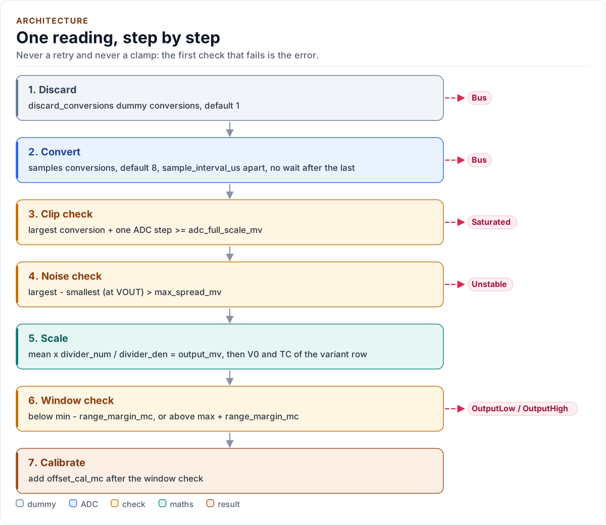
Figure description and sources
Top to bottom, each card is one step of one reading. The driver first discards dummy conversions (an ADC multiplexer's sample capacitor still holds the previous channel), then converts N times with a wait between conversions and none after the last. The next steps look at those conversions together: a conversion within one ADC step of the declared full scale means the ADC clipped, a wide spread means a floating or disturbed line, and only then are the conversions averaged, scaled by the divider and turned into a temperature with the datasheet's transfer function in one integer expression. The window check compares that temperature with the specified range plus the margin; the calibration offset is added last. The red chips on the right are the one error each step can return; the first one that applies is returned, so a conversion that failed is Bus whatever else is wrong.
Drawn from: src/mcp9700.ipp collect(); src/mcp9700.ipp Evaluate(); src/mcp9700.ipp ReadMeasurement(); figure module docs/diagrams/figures/read-pipeline.py.
- Discard.
discard_conversionsconversions whose value is thrown away. - Convert.
samplesconversions,sample_interval_usbetween every two and none after the last. A failed conversion stops the reading at once withBus: nothing is retried, and the conversions so far are dropped. - Clip check. If the largest conversion plus one ADC step reaches the declared full scale, the ADC clipped:
Saturated. The sensor's own output is far below any sensible full scale, so a clip is always a fault. - Noise check. If the largest minus the smallest conversion, scaled to VOUT, exceeds
max_spread_mv:Unstable. A floating input does this. - Scale and convert. The mean, the divider and the transfer function are one integer expression, with one rounding at the end (Transfer function).
- Window check. The temperature against the specified range plus the margin:
OutputLoworOutputHigh. - Calibrate.
offset_cal_mcis added to the temperature; the window check has already passed.
The first failing check is the error: Bus beats Saturated, which beats Unstable, which beats OutputLow and
OutputHigh. The order matters: a clipped conversion has no meaningful spread, and a floating line has no meaningful
temperature.
Start-up
EnsureInitialized() resolves the variant row, brings the port's ADC up, switches the sensor on if the port can,
waits power_on_settle_us and takes one validated reading. The reading is a weak analogue of a chip-ID check: a
plausible, stable, unclipped output on the channel rules out a dead, grounded or rail-high line, but a floating pin that
holds a stable mid-scale level passes too (see Limitations). If it fails, the
sensor is switched off again (best effort), the driver stays uninitialised, and the reason is logged and mapped to
DeviceIdMismatch (or Bus when a conversion or the port failed). A failed write of the supply pin also ends in a
best-effort switch-off, because the write may have powered the sensor.
Next: Contract.