Figures
Every figure on this site is drawn by a Python module from facts extracted from the code, so it is rebuilt,
not redrawn, when the code changes. CI runs kokeb-docs figures --check and fails when a
committed figure no longer matches the code. Each figure below lists the files it is drawn from.
Inside the MCP9700
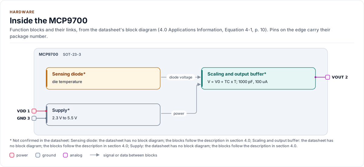
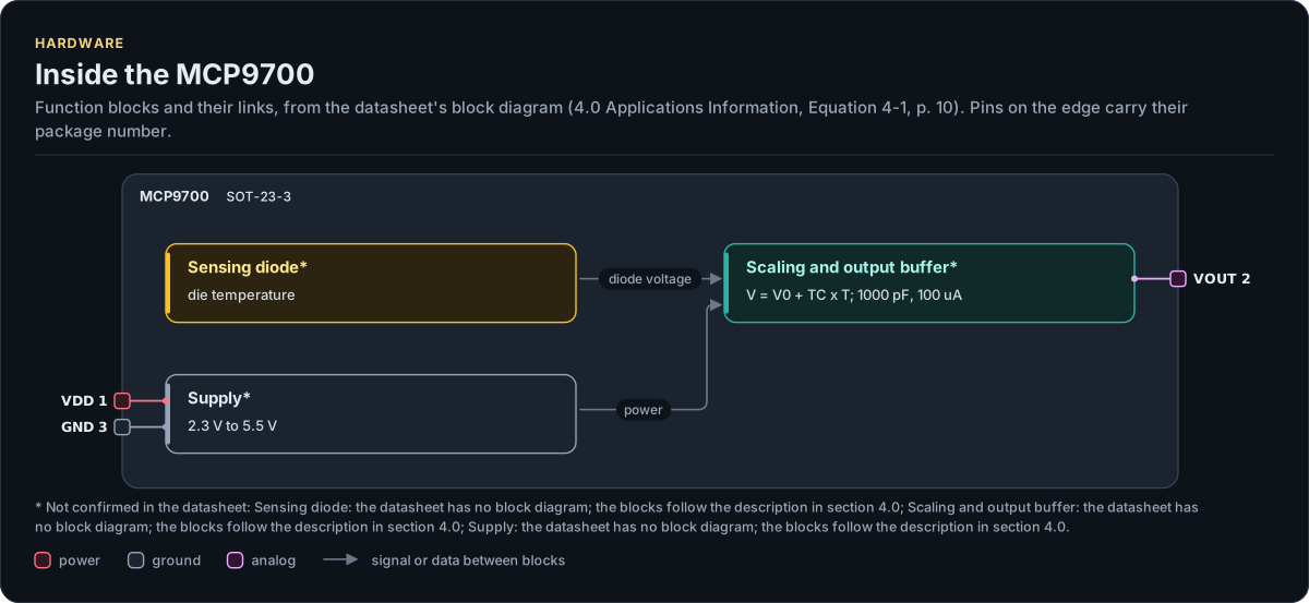
Figure description and sources
The MCP9700's function blocks inside its outline. Arrows between blocks carry signals or data in the direction they point (both ways where they have two heads). The package pins stand on the left and right edges with their numbers, each wired to the block it reaches.
Drawn from: docs/hardware.yml; inc/mcp9700.hpp; inc/mcp9700_adc_interface.hpp.
Hardware description: docs/hardware.yml
Drawn from:
MCP9700: Powered from an I/O pin
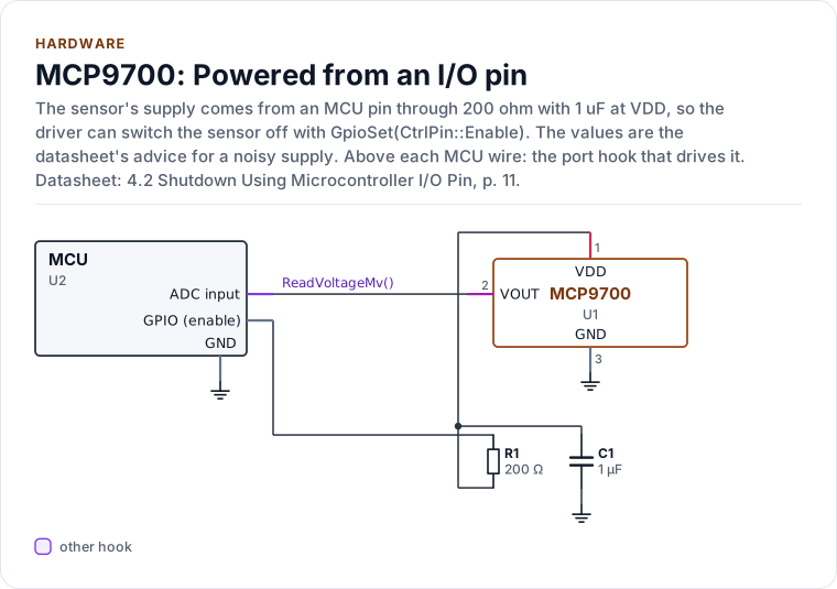
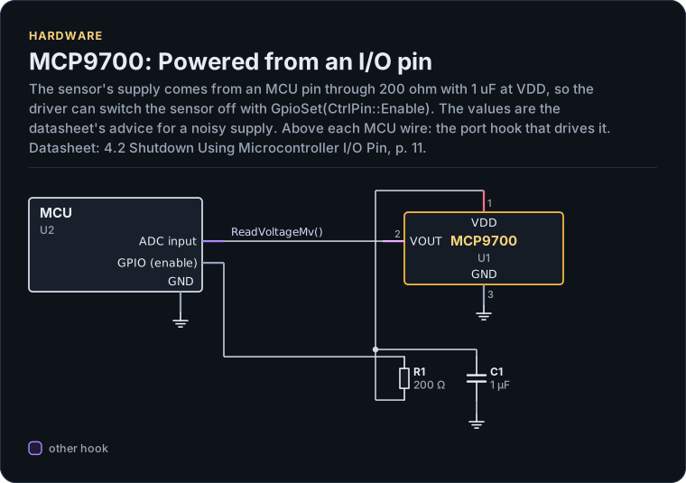
Figure description and sources
A schematic. The MCU is on the left, each of its pins level with the chip pin it connects to; above each wire is the hook of the driver's port that drives or reads it. Supply pins point up to their supply and decoupling, ground pins down. Pins on the right carry the loads and the pins tied to a supply or ground; a cross marks a pin left open. A dot is a junction; wires that cross without a dot are not connected.
Drawn from: docs/hardware.yml; inc/mcp9700.hpp; inc/mcp9700_adc_interface.hpp.
Hardware description: docs/hardware.yml
Drawn from:
MCP9700: Typical application
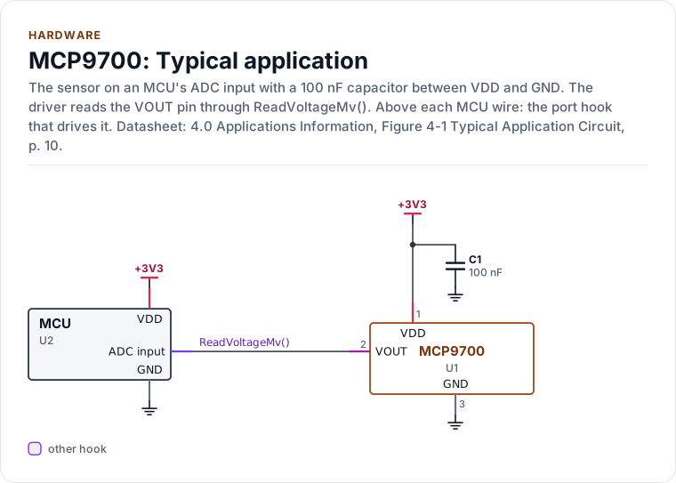
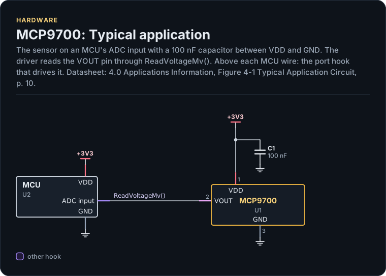
Figure description and sources
A schematic. The MCU is on the left, each of its pins level with the chip pin it connects to; above each wire is the hook of the driver's port that drives or reads it. Supply pins point up to their supply and decoupling, ground pins down. Pins on the right carry the loads and the pins tied to a supply or ground; a cross marks a pin left open. A dot is a junction; wires that cross without a dot are not connected.
Drawn from: docs/hardware.yml; inc/mcp9700.hpp; inc/mcp9700_adc_interface.hpp.
Hardware description: docs/hardware.yml
Drawn from:
MCP9700 package, SOT-23-3
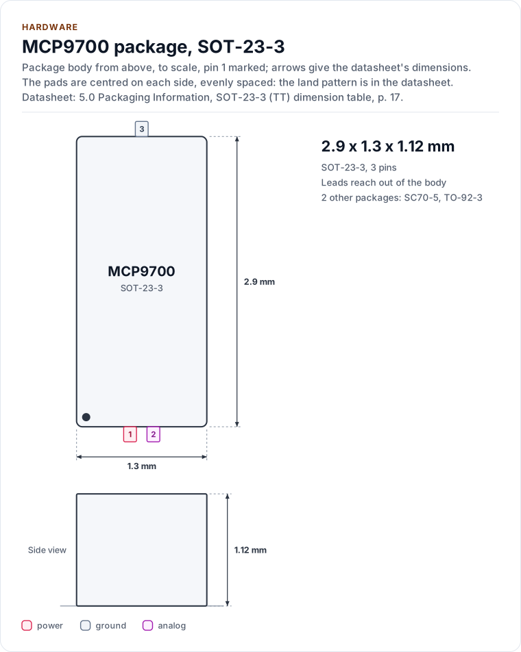
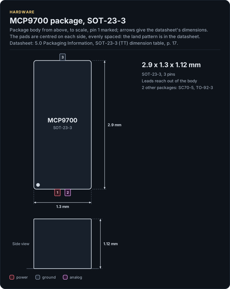
Figure description and sources
The MCP9700 package seen from the top and, when the height is known, from the side, drawn to scale: 2.9 x 1.3 x 1.12 mm. The arrows carry the datasheet's dimensions, the dot marks pin 1 and the pads are numbered counter-clockwise from it, coloured by the pin's electrical type (legend below). Pads sit centred on each side, evenly spaced; the datasheet's land pattern is the reference for a board.
Drawn from: docs/hardware.yml; inc/mcp9700.hpp; inc/mcp9700_adc_interface.hpp.
Hardware description: docs/hardware.yml
Drawn from:
MCP9700 pinout, SOT-23-3
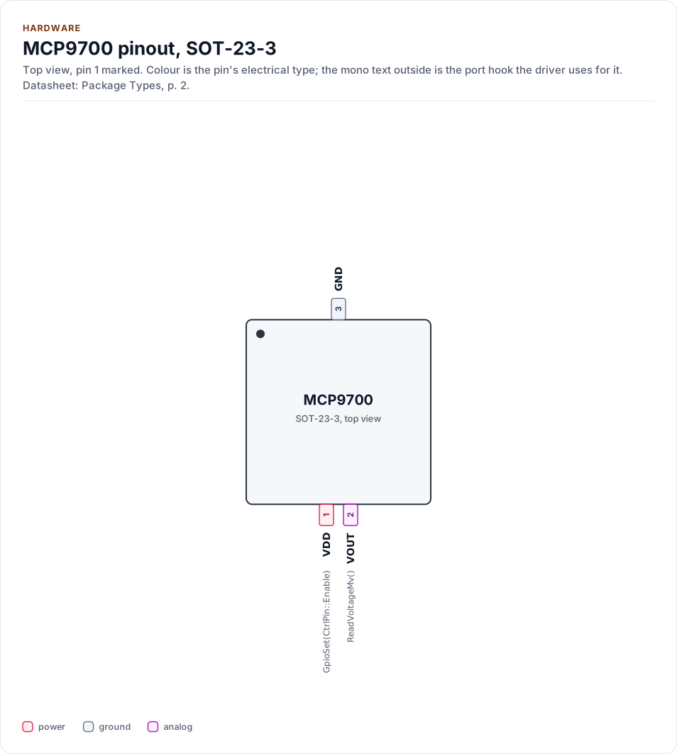
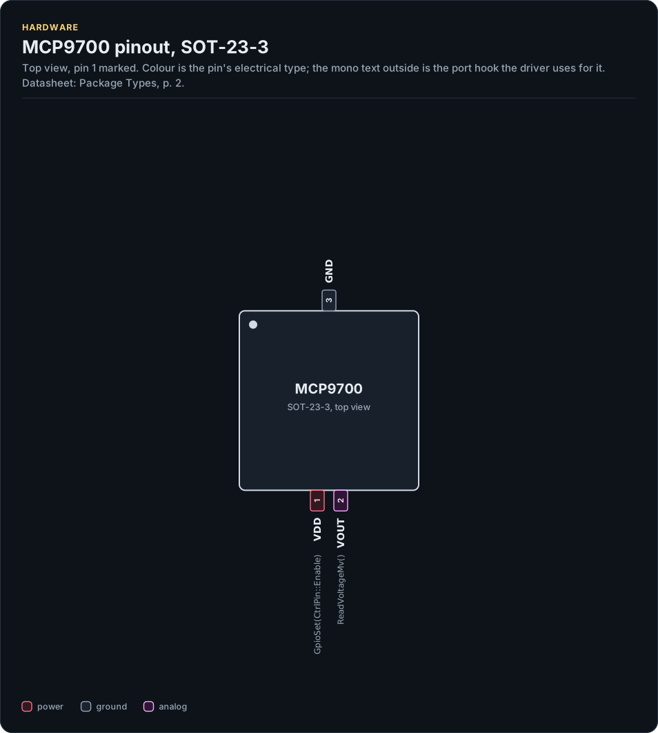
Figure description and sources
The MCP9700 seen from the top, in its SOT-23-3 package. Pin 1 is marked by the dot; the numbers run counter-clockwise from it. Each pad is coloured by the pin's electrical type (legend below). Next to it is the pin's name and, in mono, the hook of the driver's port that drives or reads it; a pin without a hook is not used by the driver.
Drawn from: docs/hardware.yml; inc/mcp9700.hpp; inc/mcp9700_adc_interface.hpp.
Hardware description: docs/hardware.yml
Drawn from:
The layers, one of them yours
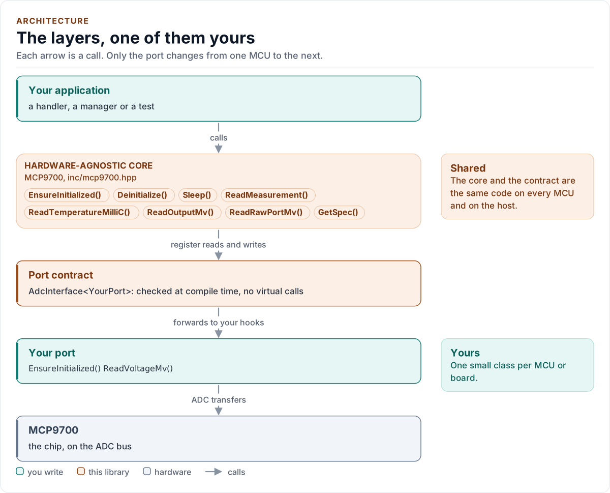
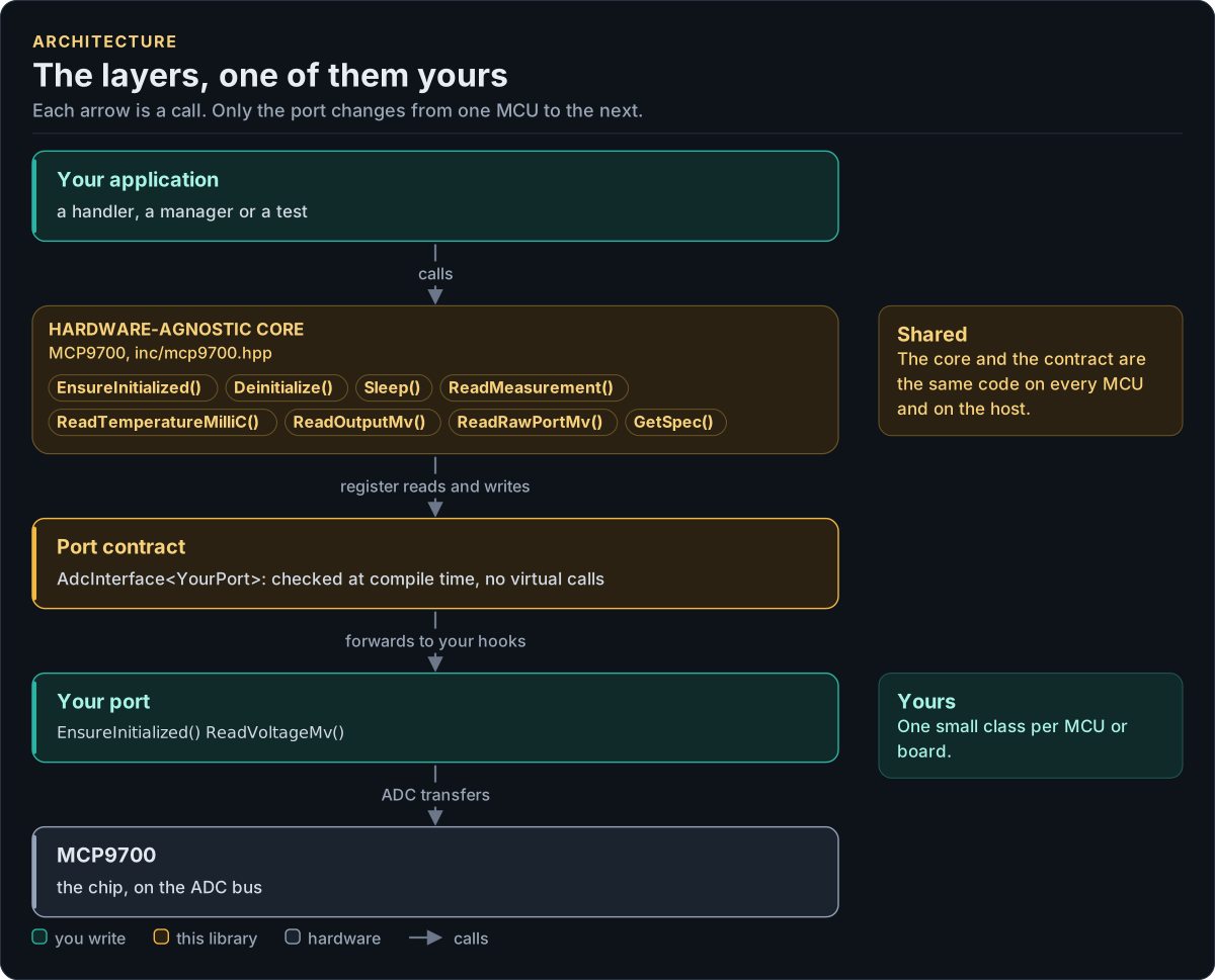
Figure description and sources
Top to bottom, each arrow is a call. Your application calls one object, whose public calls are listed from the umbrella header in inc/. The core turns each call into transfers (or, for an analog part, conversion requests) and hands them to the port contract (the CRTP base in inc/*_interface.hpp), which forwards them, at compile time, to the hooks of the port class you write; your port moves the bytes on the bus. The notes on the right say which layers stay the same on every MCU and which one you write. A library without a port contract has only the first two layers.
Drawn from: inc/mcp9700.hpp public calls; inc/mcp9700_adc_interface.hpp AdcInterface; figure module docs/diagrams/figures/driver-layers.py.
Figure module: docs/diagrams/figures/driver-layers.py
Drawn from:
public callsininc/mcp9700.hppAdcInterfaceininc/mcp9700_adc_interface.hpp
One reading, step by step
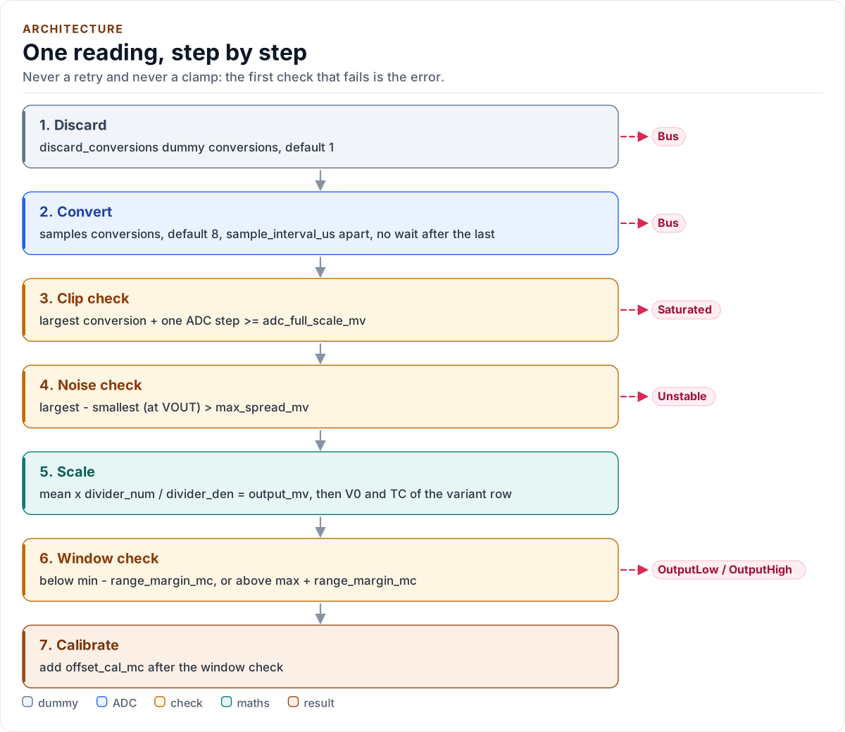
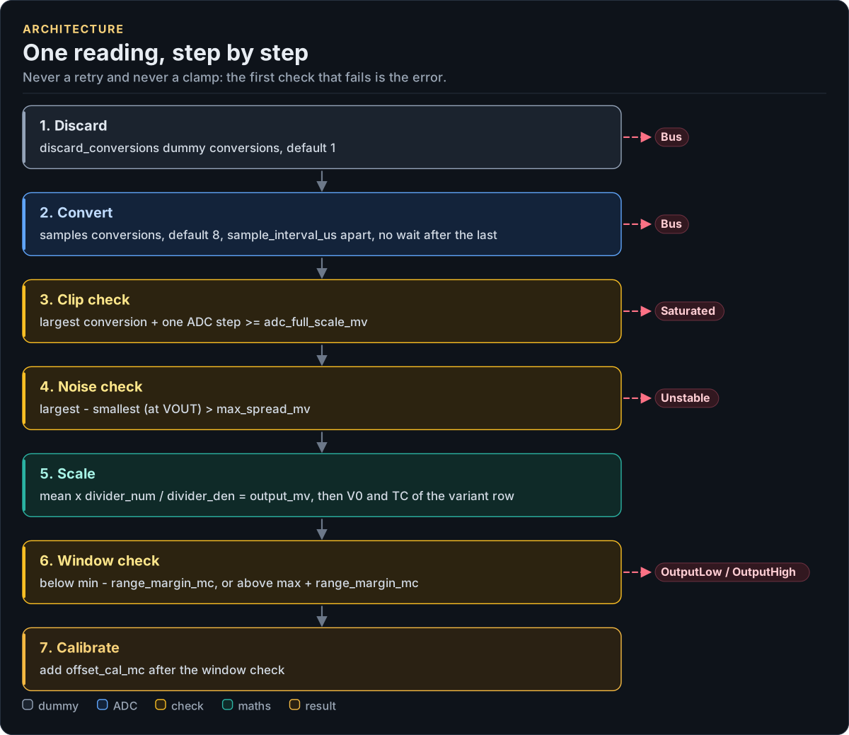
Figure description and sources
Top to bottom, each card is one step of one reading. The driver first discards dummy conversions (an ADC multiplexer's sample capacitor still holds the previous channel), then converts N times with a wait between conversions and none after the last. The next steps look at those conversions together: a conversion within one ADC step of the declared full scale means the ADC clipped, a wide spread means a floating or disturbed line, and only then are the conversions averaged, scaled by the divider and turned into a temperature with the datasheet's transfer function in one integer expression. The window check compares that temperature with the specified range plus the margin; the calibration offset is added last. The red chips on the right are the one error each step can return; the first one that applies is returned, so a conversion that failed is Bus whatever else is wrong.
Drawn from: src/mcp9700.ipp collect(); src/mcp9700.ipp Evaluate(); src/mcp9700.ipp ReadMeasurement(); figure module docs/diagrams/figures/read-pipeline.py.
Figure module: docs/diagrams/figures/read-pipeline.py
Drawn from:
collect()insrc/mcp9700.ippEvaluate()insrc/mcp9700.ippReadMeasurement()insrc/mcp9700.ipp
Output voltage against temperature
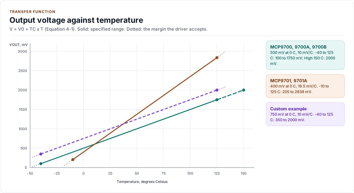
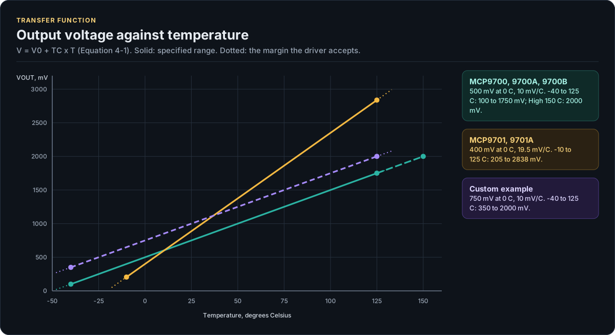
Figure description and sources
The horizontal axis is the die temperature, the vertical axis the voltage at VOUT, from Equation 4-1, V = V0 + TC x T. The MCP9700, MCP9700A and MCP9700B share the lower line (500 mV at 0 C, 10.0 mV/C); the MCP9701 and MCP9701A the steeper one (400 mV at 0 C, 19.5 mV/C). The dashed line is a Custom example from the Configuration page. Each line is solid over its specified temperature range and dotted over the plausibility margin the driver adds on each side (range_margin_mc, default 8 C): a reading outside the solid part and its dotted margin is OutputLow or OutputHigh, never a temperature. The dots mark the ends of the specified range and the voltage there.
Drawn from: inc/mcp9700_types.hpp kVariantTable; inc/mcp9700_types.hpp range_margin_mc; tests/docs/configuration.cpp custom-offset; figure module docs/diagrams/figures/transfer-function.py.
Figure module: docs/diagrams/figures/transfer-function.py
Drawn from:
kVariantTableininc/mcp9700_types.hpprange_margin_mcininc/mcp9700_types.hppcustom-offsetintests/docs/configuration.cpp