Architecture
How the driver is built: three layers, one of them yours, the two-phase access every call is made of, and the copy of the chip's registers the driver keeps.
Datasheet sections this page relies on
From Analog Devices 19-100531 1:
- The SPI, the 8-bit accesses and the daisy chain: SPI Detailed Description; Figure 5, p. 23
- The programming procedure: Programming Procedure; Figure 6, p. 23
- The Command Register and the fault byte: Command Register Description (COMMAND); Table 9; Figure 7, p. 25
- 32-bit and 8-bit transfers and the command echo: Reading and Writing Operations of Registers; Figures 10 to 13, p. 30
- Register map and reset values: Register Map; Register Details, p. 35
All of them, with the driver API for each: Datasheet map.
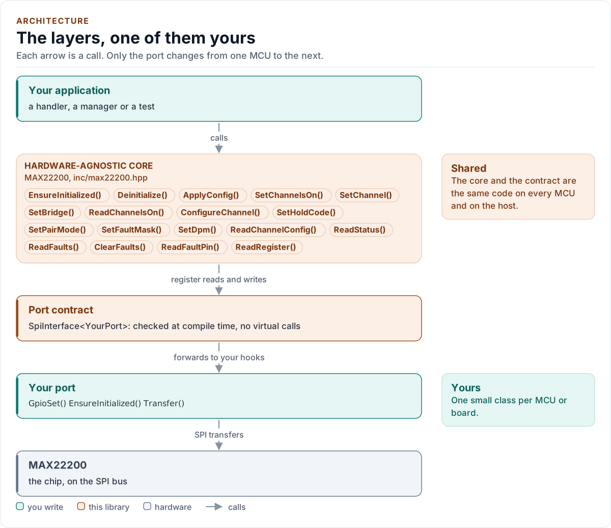
Figure description and sources
Top to bottom, each arrow is a call. Your application calls one object, whose public calls are listed from the umbrella header in inc/. The core turns each call into register reads and writes and hands them to the port contract (the CRTP base in inc/*_interface.hpp), which forwards them, at compile time, to the hooks of the port class you write; your port moves the bytes on the bus. The notes on the right say which layers stay the same on every MCU and which one you write. A library without a port contract has only the first two layers.
Drawn from: inc/max22200.hpp public calls; inc/max22200_spi_interface.hpp SpiInterface; figure module docs/diagrams/figures/driver-layers.py.
Layers
| Layer | Files | Owns |
|---|---|---|
| Core | inc/max22200.hpp, src/max22200.ipp |
Lifecycle, the programming procedure, the register copy, the checks, errors |
| Types and registers | inc/max22200_types.hpp, inc/max22200_registers.hpp |
Error, Result<T>, Config, the encodings, the unit conversions, Validate(); the register map |
| Port contract | inc/max22200_spi_interface.hpp |
The CRTP base, CtrlPin and GpioSignal, the SpiPort concept, the two-phase access |
| Platform port | Your class | Bus bring-up, byte transfers, CMD and ENABLE, the delay; optionally the FAULT pin and logging |
| Kconfig layer | inc/max22200_kconfig.hpp |
Optional: a Config from ESP-IDF menuconfig |
One access, two transfers
The chip has one 8-bit Command Register and four kinds of 32-bit register: STATUS, CFG_CH0 to CFG_CH7, FAULT and CFG_DPM. Every access is two SPI transfers ("Command Register Description", Figures 7 and 10 to 13):
| Transfer | CMD | SDI | SDO |
|---|---|---|---|
| 1. Command | high, also at the CSB rising edge | RB/W, A_BNK (bank), 8bit/n32bits | STATUS[7:0], the fault byte |
| 2a. Write 32 bits | low | DATAIN[7:0], [15:8], [23:16], [31:24]: LSB byte first | STATUS[7:0], the command, 0, 0 |
| 2b. Read 32 bits | low | 0 (FAULT: the flags to clear, LSB byte first) | DATA[31:24], [23:16], [15:8], [7:0]: MSB byte first |
| 2c. Write 8 bits | low | DATAIN[31:24] | STATUS[7:0] |
| 2d. Read 8 bits | low | DATA[31:24] |
detail::RegisterBus does this and nothing else. It drives CMD high only if the port can (a command sent with CMD
low would be taken as data), and drives it low again after every command byte. The fault byte of every command is
kept (GetLastStatusByte()); the command echo of a 32-bit write is checked at start-up and with
Verify::ReadBack.
The 8-bit accesses are the fast paths the datasheet names: ONCH (switching, SetChannelsOn()) and HFS/HOLD
(SetHoldCode()), one byte each.
One call through the layers
sequenceDiagram
    participant App as Your code
    participant Core as MAX22200<Port>
    participant Port as Your port
    App->>Core: SetChannel(2, true)
    Note over Core: next = copy of ONCH | 0x04
    Core->>Port: GpioSet(Cmd, ACTIVE)
    Core->>Port: Transfer(0x81): write STATUS, 8 bit
    Port-->>Core: true, fault byte
    Core->>Port: GpioSet(Cmd, INACTIVE)
    Core->>Port: Transfer(next)
    Port-->>Core: true
    Note over Core: copy of ONCH = next
    Core-->>App: Result<void>{Ok}
The register copy
The driver keeps what it wrote: the Config (STATUS fields, every CFG_CHn, CFG_DPM) and ONCH. It needs the copy
because:
- STATUS holds ONCH and the configuration together, so a 32-bit STATUS write (a pair mode, the masks) must carry the
current ONCH, and a single-channel switch must know the other seven without reading STATUS. A read would cost two
transfers and clear OVT and UVM as a side effect (every STATUS read the driver does make keeps them in the latch
of
GetLatchedFaults()). - The chip ignores a drive-mode or side change while a channel is on, and a pair-mode change while one of the pair is
on; the driver refuses them up front (
ChannelsActive) from the copy. After a failed ONCH write the channels it would have changed count as on for this check, because the chip may have taken the write. - The 8-bit HOLD write must carry the channel's HFS bit.
The copy is what the driver wrote, not what the chip holds: ReadStatus(), ReadChannelsOn(),
ReadChannelConfig() and Verify::ReadBack read the chip.
Design choices
- CRTP, not virtual functions. The port is a template parameter constrained by the
SpiPortconcept, so every call is resolved at compile time and a missing hook is a compile error that names it. - Required pins in the port. CMD is part of the protocol, so
GpioSet()is required and must returnbool; a failed pin write is reported asPin, never ignored. - Optional hooks by
requires.GpioRead(the FAULT pin) andLogare detected with C++20requiresin one place; without themReadFaultPin()returnsUnsupportedand nothing is logged. - Codes, not floats, in the configuration.
ChannelConfigholds the register's codes; the conversions from milliamps and microseconds are exact integer functions that refuse a value the chip cannot do safely. - No I/O in the constructor. Construction cannot fail, so the driver can be a static or a member of a handler.
- One error type.
Result<T>carries a value and anError; nothing throws and nothing returns a barebool. - No heap, no exceptions, no RTTI, no
std::function, noprintf. The driver is a header-only template with no mutable static state.
Source map
| You want | Read |
|---|---|
| The public API | inc/max22200.hpp |
| How a call is implemented | src/max22200.ipp |
| Register banks, bits and timing | inc/max22200_registers.hpp |
| The settings, encodings and conversions | inc/max22200_types.hpp |
| The port contract and the two-phase access | inc/max22200_spi_interface.hpp |
Next: Contract.