Hardware
How a DYNAMIXEL servo bus is wired and timed, as the driver uses it: the connector, the half-duplex data line, the bus settings, the timing and the supply.
The driver talks to a family of servos, not to one chip. The reference part of this page is the XM430-W350; the other families differ in the connector housing and the supply range (Control tables). Not verified on hardware: everything here follows the ROBOTIS e-Manual, which is a set of web pages (see the Datasheet map).
Datasheet sections this page relies on
- Half duplex line and Tx/Rx direction: ROBOTIS e-Manual, DYNAMIXEL Protocol 2.0 web page, no revision mark, 1.4 Half Duplex; 1.5 Tx, Rx Direction, p. 1
- Specifications, baud rates and ID range: ROBOTIS e-Manual, XM430-W350 web page, no revision mark, 1 Specifications, p. 1
- Connector, power and communication circuit: ROBOTIS e-Manual, XM430-W350 web page, no revision mark, 4.5 Connector Information; 4.6 Communication Circuit, p. 1
- Connector and half-duplex circuit, protocol 1.0 servos: ROBOTIS e-Manual, AX-12A web page, no revision mark, 5.2 Connector Information; 5.4 Communication Circuit, p. 1
All of them, with the driver API for each: Datasheet map.
The servos need their own supply
The XM430-W350 runs from 10.0 V to 14.8 V (12.0 V recommended) and draws amperes when it moves. Never power it from the MCU board. The TTL connector carries a single TTL data line (the e-Manual's text gives no voltage level; its circuit figure pulls the line up to 5 V, see Circuits below); the RS-485 variant is differential and needs a transceiver.
Pins
The 3-pin TTL connector of the X series (JST EH) carries ground, the supply and one half-duplex data line. The RS-485 variant has the same first two pins and splits the data into DATA+ and DATA-.
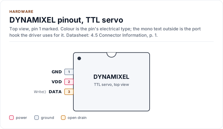
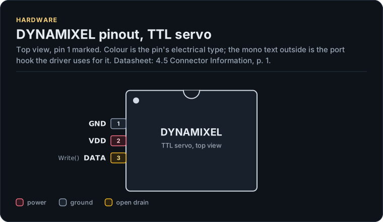
Figure description and sources
The DYNAMIXEL seen from the top, in its TTL servo package. Pin 1 is marked by the dot; the numbers run counter-clockwise from it. Each pad is coloured by the pin's electrical type (legend below). Next to it is the pin's name and, in mono, the hook of the driver's port that drives or reads it; a pin without a hook is not used by the driver.
Drawn from: docs/hardware.yml; inc/dynamixel_uart_interface.hpp.
TTL servo, 3 pins (4.5 Connector Information, p. 1).
| Pin | Name | Type (domain) | Function | Driver hook | Datasheet |
|---|---|---|---|---|---|
| 1 | GND |
ground | Ground and the negative supply (pin 1 of the connector) | - | 4.5, p. 1 |
| 2 | VDD |
power (VDD) | Positive supply, 10.0 V to 14.8 V, 12.0 V recommended (XM430-W350) | - | 1, p. 1 |
| 3 | DATA |
open drain (TTL, 5 V in the circuit) | Half-duplex TTL data line, 8N1: the master and every servo share it. The master's TX and RX meet here (single wire), so a sent byte is also read back unless the adapter gates it. The page text gives no voltage level; the circuit figure shows a 10 kOhm pull-up to 5 V. Unverified: the drive type (open drain) is not stated | Write() |
4.5, p. 1 |
Source of this table and of the chip figures: docs/hardware.yml.
The driver has no pin of its own to drive: the only hooks are Write() and Read() of your UART port. The
direction of the half-duplex stage is part of Write() (Porting).
The data line
All servos and the master share one data line. The master sends an instruction packet; the addressed servo answers with a status packet after its Return Delay Time (500 microseconds at the factory value, up to 508). Between the two the line must be turned round: the master stops driving it and listens.
| Wiring | How the direction is switched | Port | Config::echo |
|---|---|---|---|
| UART with a direction pin (RS-485 transceiver, tri-state buffer) | The UART's RTS output or a GPIO, high while sending | Write() raises it, sends, waits for the last stop bit and lowers it |
None |
UART with a hardware half-duplex mode (ESP32 UART_MODE_RS485_HALF_DUPLEX) |
The hardware, with the first start bit and after the last stop bit | Write() sends and waits for the transmitter to be done |
None |
| TX and RX tied to the single wire (open-drain or diode stage) | None: the master's own bytes come back on RX | Write() leaves the echo in the receive FIFO |
Loopback |
With EchoMode::Loopback the driver reads the echo of every packet it sent and compares it with the request:
another talker on the line, or a short, shows as Error::EchoMismatch before any reply is waited for.
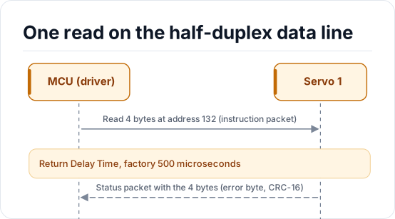
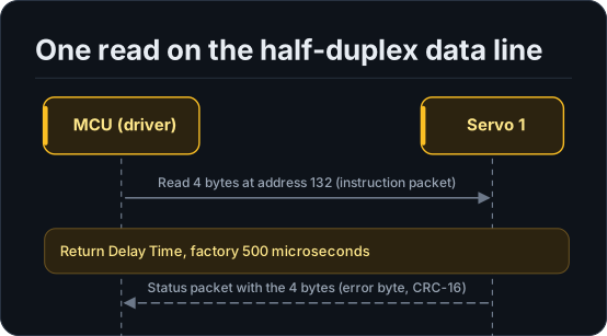
Figure description and sources
Participants, left to right: MCU (driver) and Servo 1. The steps run from top to bottom. MCU (driver) sends Read 4 bytes at address 132 (instruction packet) to Servo 1. A note over MCU (driver) and Servo 1 says: Return Delay Time, factory 500 microseconds. Servo 1 returns Status packet with the 4 bytes (error byte, CRC-16) to MCU (driver).
Drawn from: docs/model/data-line-read.seq.yml.
Bus settings
| Setting | Value |
|---|---|
| UART format | 8 data bits, no parity, 1 stop bit |
| Bit rate | About 7 800 (AX-12A) or 9 600 to 4 500 000 bit/s on the catalogued families; factory 57 600 (X series) or 1 000 000 (protocols 1.0 families); every servo on the bus must run the same rate |
| Packet | Protocol 1.0 or 2.0, the same for every servo on the bus (Protocol) |
| Byte gap inside an instruction | At most 1.5 ms in protocol 2.0 and 100 ms in protocol 1.0, or the servo drops the packet: Write() sends the packet in one go |
| IDs | 0 to 252 (2.0) or 0 to 253 (1.0); 254 is the broadcast ID; every ID on a bus must be unique |
The factory bit rate and ID differ by family: an X-series servo comes at ID 1 and 57 600 bit/s, an AX-12A at ID 1
and 1 000 000 bit/s. Config::baud must match; a wrong rate looks like silence (Error::Timeout) or noise.
Circuits
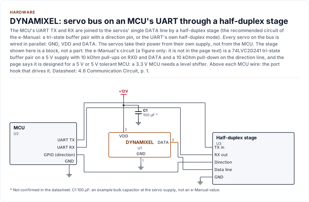
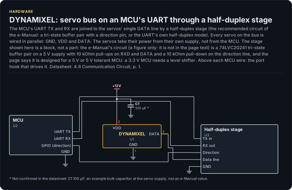
Figure description and sources
A schematic. The MCU is on the left, each of its pins level with the chip pin it connects to; above each wire is the hook of the driver's port that drives or reads it. Supply pins point up to their supply and decoupling, ground pins down. Pins on the right carry the loads and the pins tied to a supply or ground; a cross marks a pin left open. A dot is a junction; wires that cross without a dot are not connected.
Drawn from: docs/hardware.yml; inc/dynamixel_uart_interface.hpp.
The e-Manual's recommended TTL circuit is a pair of tri-state buffers (a 74LVC2G241 in the figure), one for each
direction. One direction signal (TX_Enable) drives both enables: low enables the receive buffer (servo DATA to the
MCU's RXD), high enables the transmit buffer (the MCU's TXD to DATA). The circuit is a figure only: the page text says
that it "is designed for 5V or 5V tolerant MCU. Otherwise, use a Level Shifter to match the voltage of MCU", and the
figure runs the buffers from 5 V. It has a 10 kilohm pull-up to 5 V on the RXD node and on the DATA node, and a 10
kilohm pull-down to ground on TX_Enable, so that the stage listens while the MCU pin is not driven. Do not
copy the enable resistor as a pull-up: a pull-up on the direction pin would enable the transmit buffer and drive DATA
high at idle, against the servos' own answers. A 3.3 V MCU therefore needs a level shifter; the e-Manual shows no
3.3 V circuit. What is read from the figure (the part name, the 5 V supply, the pull-ups and the pull-down) is
unverified against a second source. The stage drawn here is a block, not a part; any circuit that gives
the same behaviour (an RS-485 transceiver with the right level, or a UART's own half-duplex mode) works the same way
for the driver. Add a bulk capacitor on the servo supply; the 100 microfarad of the drawing is an example, not a
datasheet value.
Inside the servo
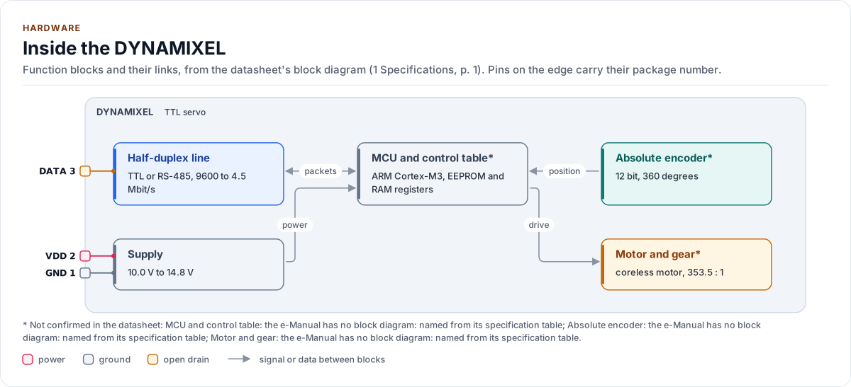
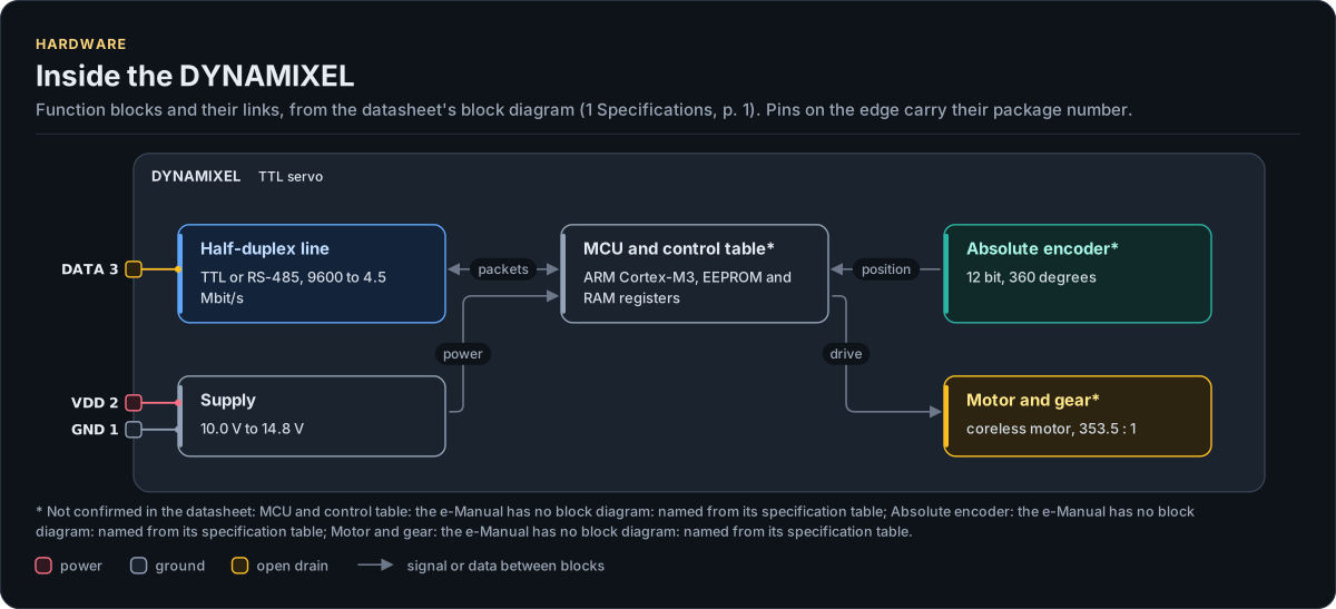
Figure description and sources
The DYNAMIXEL's function blocks inside its outline. Arrows between blocks carry signals or data in the direction they point (both ways where they have two heads). The package pins stand on the left and right edges with their numbers, each wired to the block it reaches.
Drawn from: docs/hardware.yml; inc/dynamixel_uart_interface.hpp.
The e-Manual has no block diagram; this one is drawn from its specification table, and the blocks are marked as
unverified in hardware.yml.
Mechanical
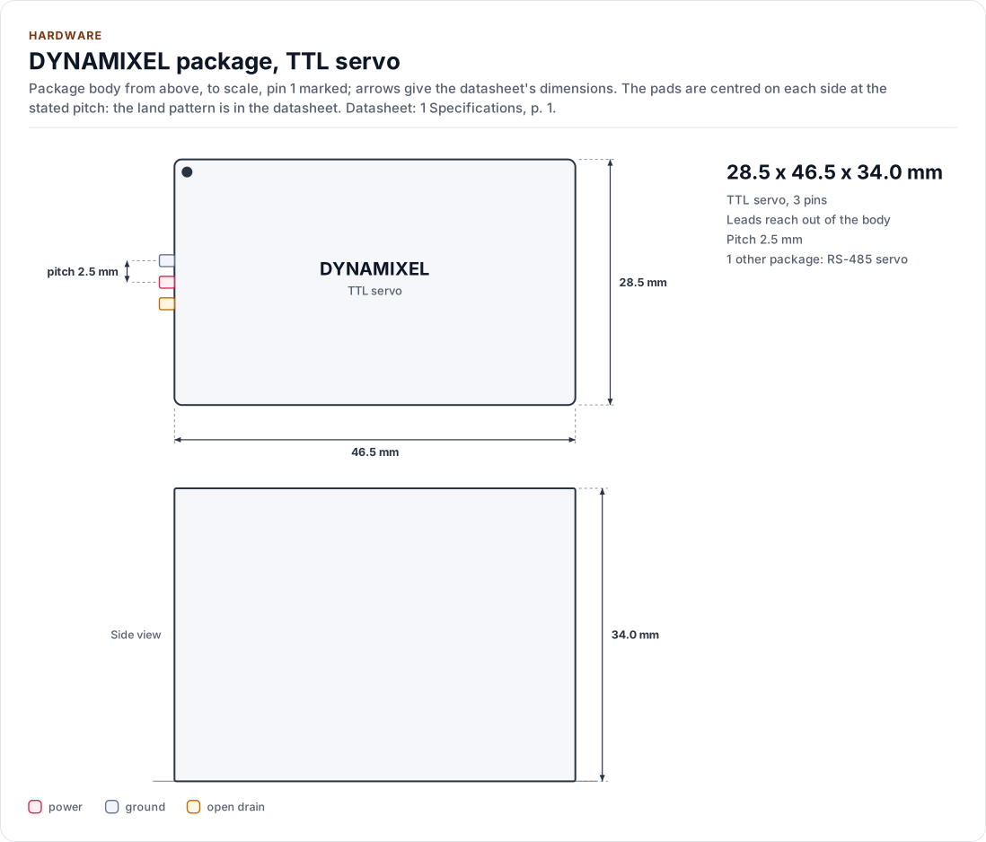
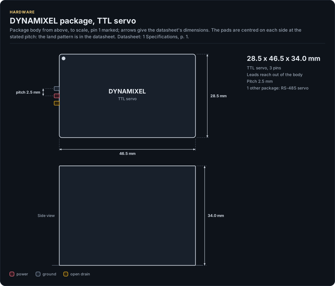
Figure description and sources
The DYNAMIXEL package seen from the top and, when the height is known, from the side, drawn to scale: 28.5 x 46.5 x 34.0 mm. The arrows carry the datasheet's dimensions, the dot marks pin 1 and the pads are numbered counter-clockwise from it, coloured by the pin's electrical type (legend below). Pads sit centred on each side at the stated pitch; the datasheet's land pattern is the reference for a board.
Drawn from: docs/hardware.yml; inc/dynamixel_uart_interface.hpp.
Timing
| Parameter | Value | Driver |
|---|---|---|
| Return Delay Time | 500 microseconds at the factory value, at most 508 (register, 2 microsecond counts) | kTurnaroundUs, kMaxTurnaroundUs; Config::reply_timeout_us must be longer |
| Reply wait | Not specified by the e-Manual | Config::reply_timeout_us, 20 ms by default (100 microseconds to 1 s) |
| Wait inside a packet | Not specified | Config::gap_timeout_us, 5 ms by default |
| Reboot, restore, factory reset | The servo restarts after its reply | Config::reboot_wait_us, 500 ms by default |
| Baud rate change | The servo switches after the reply | Config::baud_change_wait_us, 10 ms by default |
| Broadcast ping | The servos answer in ID order | Config::broadcast_timeout_us per reply, 100 ms by default |
A byte takes ten bit times: 174 microseconds at 57 600 bit/s, 10 microseconds at 1 Mbit/s. A Fast Sync Read of
many servos at a low rate needs a reply_timeout_us that covers the whole packet; the driver waits per read, not
for the whole packet (Configuration).
Power
| Quantity | XM430-W350 |
|---|---|
| Supply voltage | 10.0 V to 14.8 V, 12.0 V recommended |
| Stall current | 2.1 A at 11.1 V, 2.3 A at 12.0 V |
| Standby current | 40 mA |
The servo reports its input voltage in 0.1 V counts (Reg::PresentInputVoltage; it shows in ReadFeedback()).
Other families run from 5 V to 12 V or more; check the e-Manual page of the model.
Reference documents
The datasheets are the ROBOTIS e-Manual pages for protocols 1.0 and 2.0 and for the models of the catalogue. Every
pin, setting and timing on this page cites a section; the revision, the SHA-256 of the saved HTML and the sections
each page relies on are in docs/datasheets.yml.
| Document | Revision | Get it |
|---|---|---|
| Protocol specification: DYNAMIXEL Protocol 2.0 (e-Manual) (ROBOTIS e-Manual, DYNAMIXEL Protocol 2.0) | web page, no revision mark, 2026-11-12 | vendor page |
| Protocol specification: DYNAMIXEL Protocol 1.0 (e-Manual) (ROBOTIS e-Manual, DYNAMIXEL Protocol 1.0) | web page, no revision mark, 2026-11-12 | vendor page |
| Protocol specification: CRC Calculation (e-Manual) (ROBOTIS e-Manual, CRC Calculation) | web page, no revision mark, 2026-11-12 | vendor page |
| Servo manual: XM430-W350 (e-Manual): the X series reference (ROBOTIS e-Manual, XM430-W350) | web page, no revision mark, 2026-11-12 | vendor page |
| Servo manual: AX-12A (e-Manual): the protocol 1.0 reference (ROBOTIS e-Manual, AX-12A) | web page, no revision mark, 2026-11-12 | vendor page |
| Servo manual: XL-320 (e-Manual) (ROBOTIS e-Manual, XL-320) | web page, no revision mark, 2026-11-12 | vendor page |
Written against these revisions; the SHA-256 of each file is in docs/datasheets.yml. Where each part
of the driver is in the datasheet: Datasheet map.
| Also useful | Contents |
|---|---|
inc/dynamixel_tables.hpp |
The control table of every family, with the e-Manual page of each |
inc/dynamixel_protocol.hpp |
The packet layout, stuffing, CRC and the reply search |