Figures
Every figure on this site is drawn by a Python module from facts extracted from the code, so it is rebuilt,
not redrawn, when the code changes. CI runs kokeb-docs figures --check and fails when a
committed figure no longer matches the code. Each figure below lists the files it is drawn from.
Inside the BNO08x
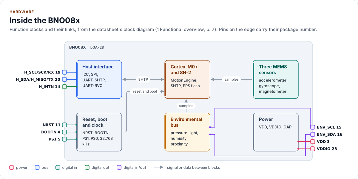
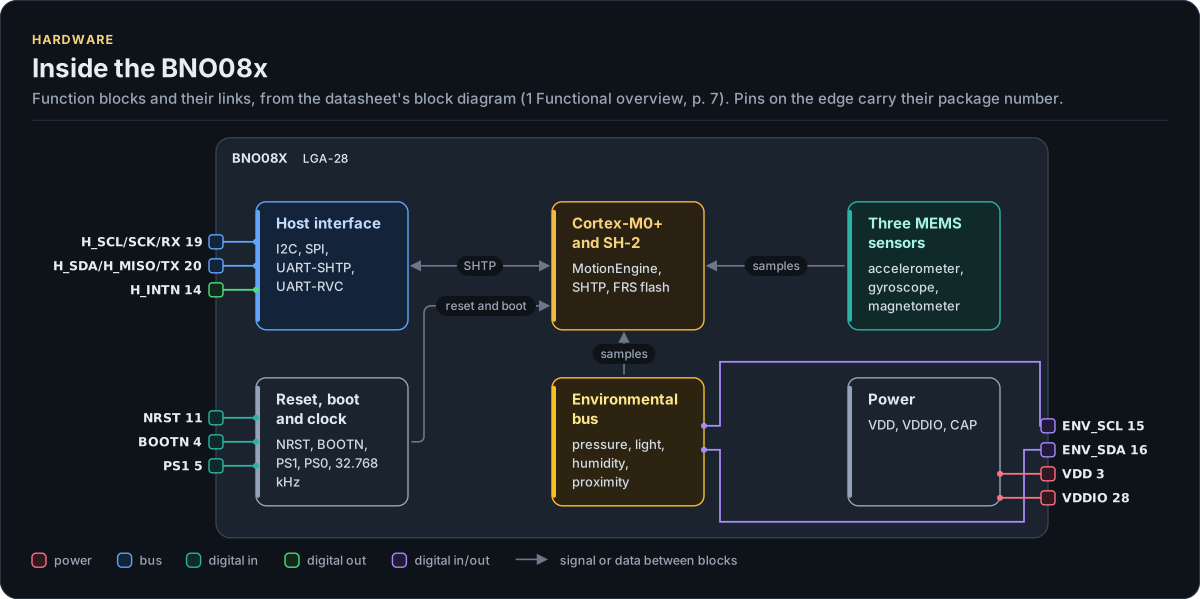
Figure description and sources
The BNO08x's function blocks inside its outline. Arrows between blocks carry signals or data in the direction they point (both ways where they have two heads). The package pins stand on the left and right edges with their numbers, each wired to the block it reaches.
Drawn from: docs/hardware.yml; inc/bno08x_interface.hpp.
Hardware description: docs/hardware.yml
Drawn from:
BNO08x: I2C
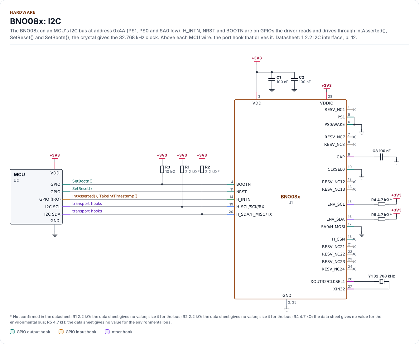
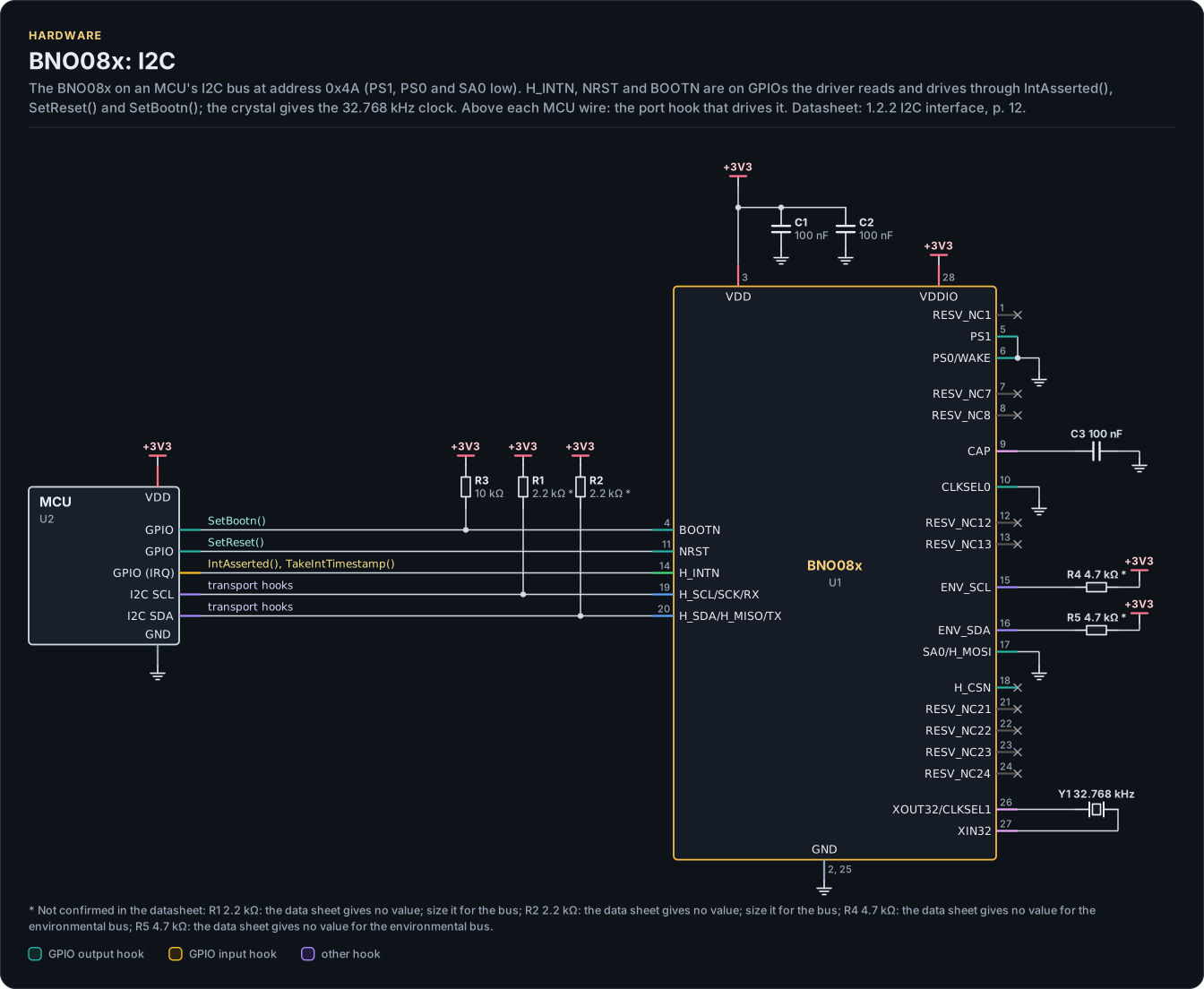
Figure description and sources
A schematic. The MCU is on the left, each of its pins level with the chip pin it connects to; above each wire is the hook of the driver's port that drives or reads it. Supply pins point up to their supply and decoupling, ground pins down. Pins on the right carry the loads and the pins tied to a supply or ground; a cross marks a pin left open. A dot is a junction; wires that cross without a dot are not connected.
Drawn from: docs/hardware.yml; inc/bno08x_interface.hpp.
Hardware description: docs/hardware.yml
Drawn from:
BNO08x: SPI
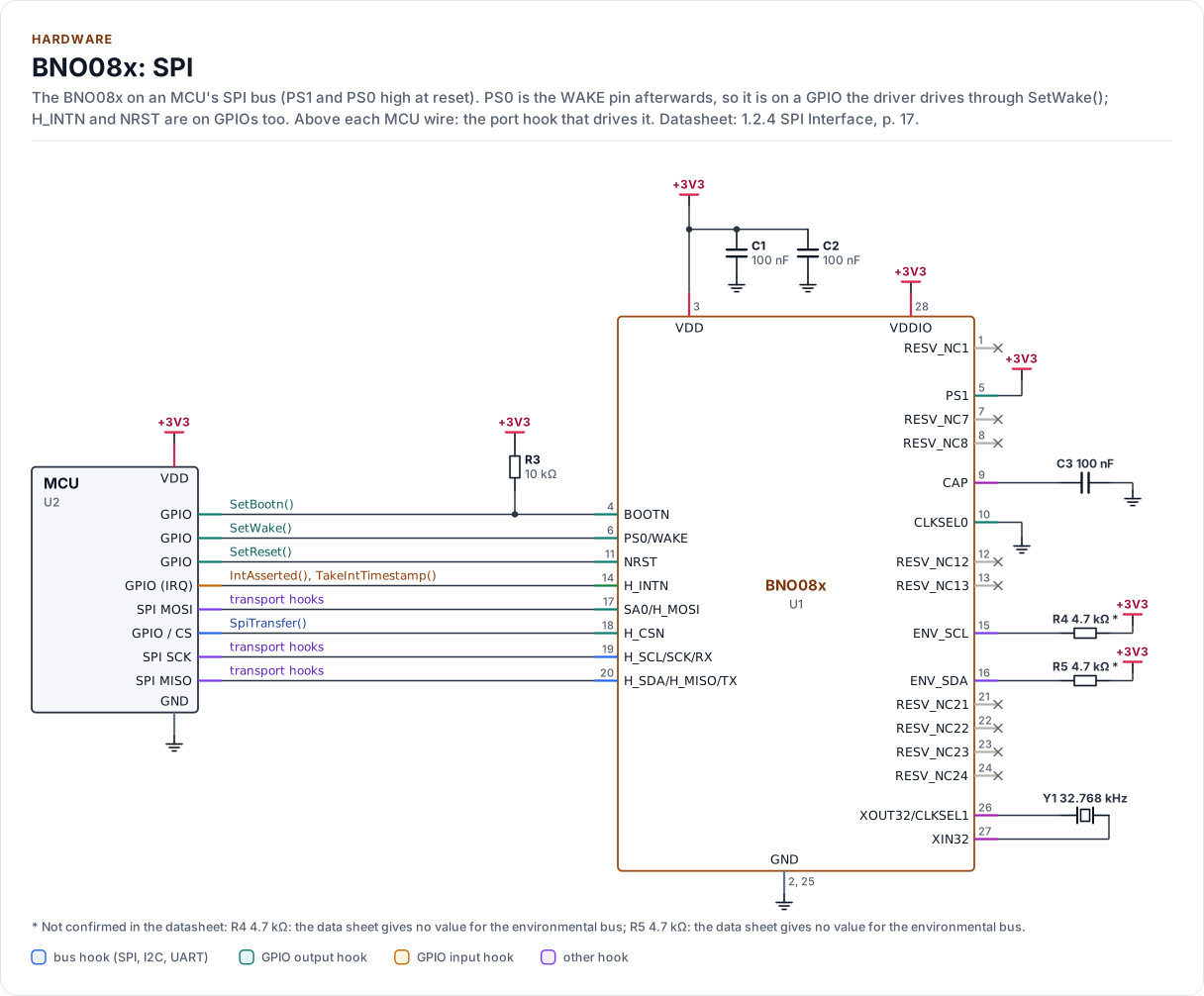
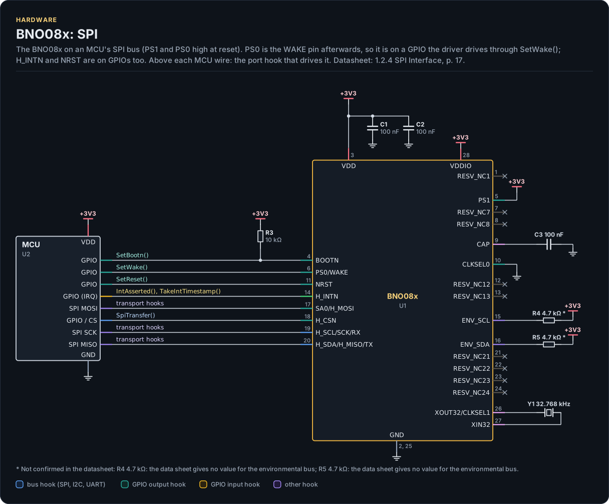
Figure description and sources
A schematic. The MCU is on the left, each of its pins level with the chip pin it connects to; above each wire is the hook of the driver's port that drives or reads it. Supply pins point up to their supply and decoupling, ground pins down. Pins on the right carry the loads and the pins tied to a supply or ground; a cross marks a pin left open. A dot is a junction; wires that cross without a dot are not connected.
Drawn from: docs/hardware.yml; inc/bno08x_interface.hpp.
Hardware description: docs/hardware.yml
Drawn from:
BNO08x: UART-RVC
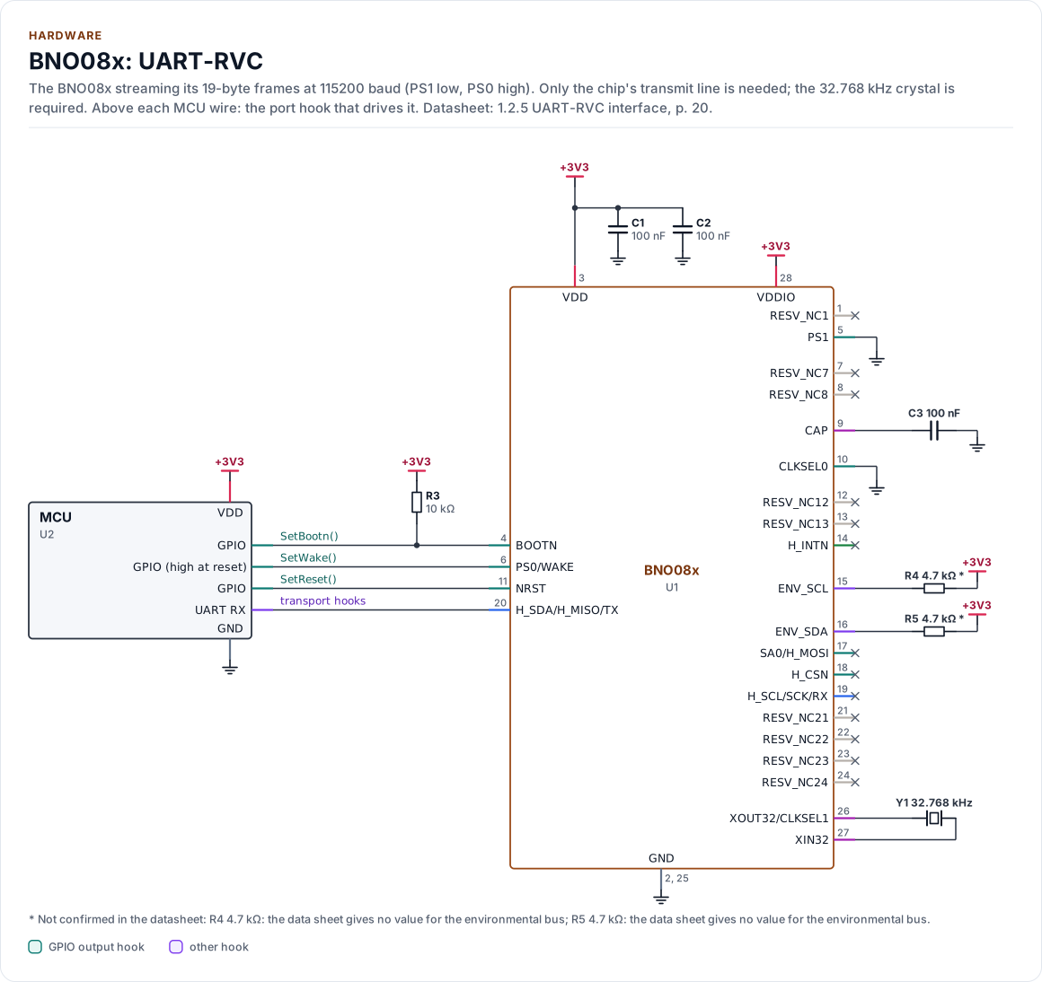
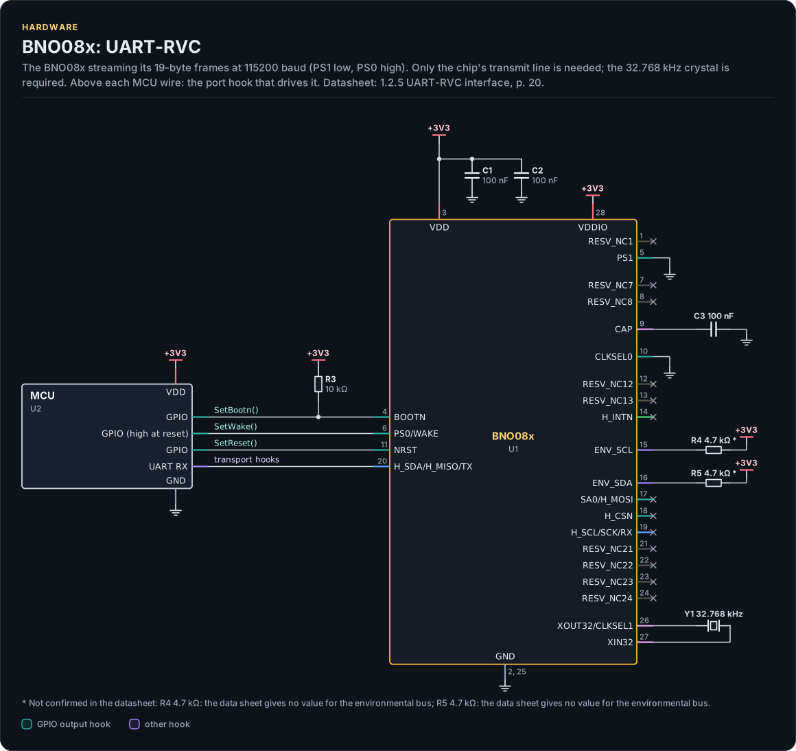
Figure description and sources
A schematic. The MCU is on the left, each of its pins level with the chip pin it connects to; above each wire is the hook of the driver's port that drives or reads it. Supply pins point up to their supply and decoupling, ground pins down. Pins on the right carry the loads and the pins tied to a supply or ground; a cross marks a pin left open. A dot is a junction; wires that cross without a dot are not connected.
Drawn from: docs/hardware.yml; inc/bno08x_interface.hpp.
Hardware description: docs/hardware.yml
Drawn from:
BNO08x: UART-SHTP
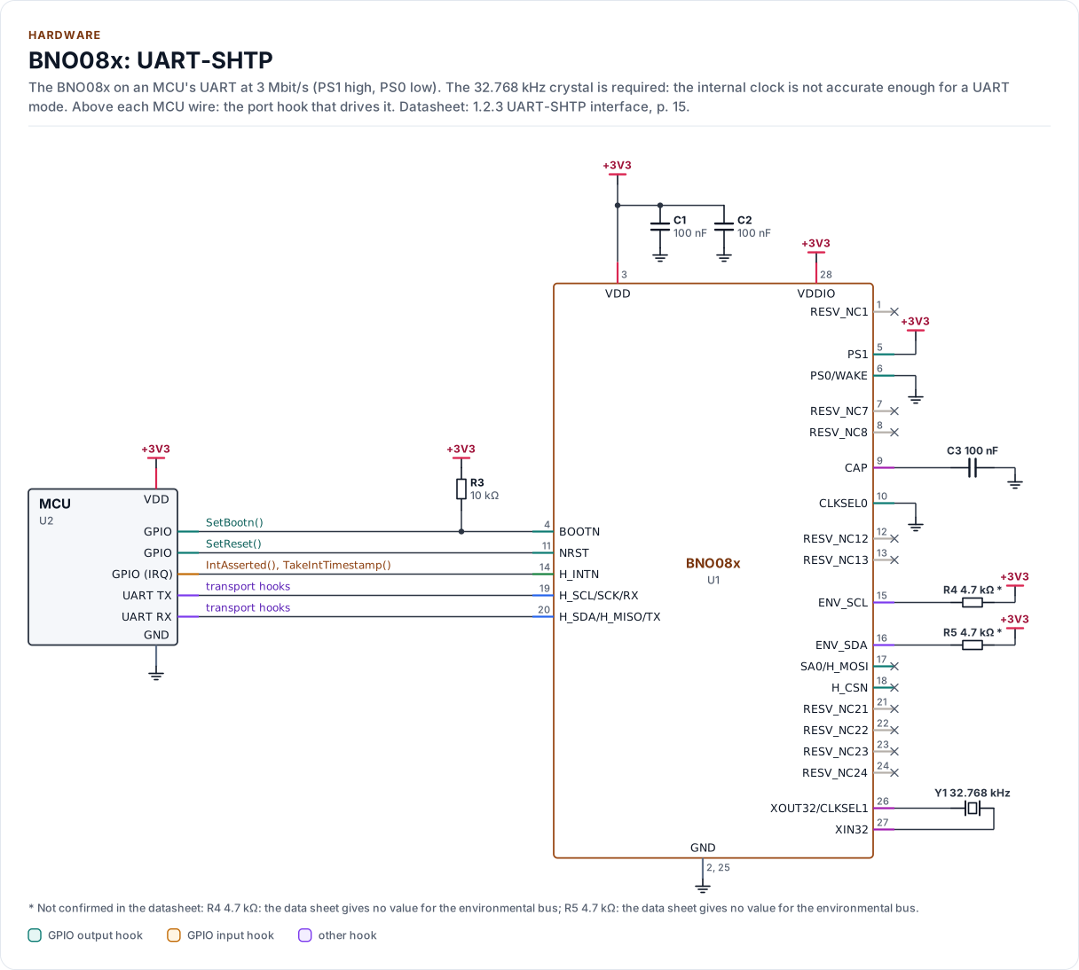
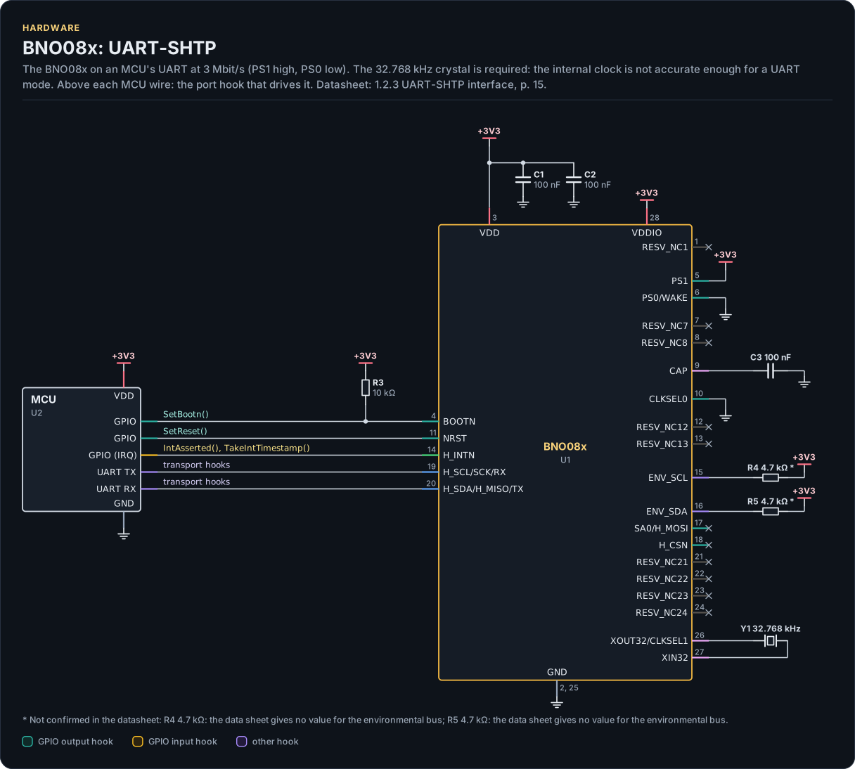
Figure description and sources
A schematic. The MCU is on the left, each of its pins level with the chip pin it connects to; above each wire is the hook of the driver's port that drives or reads it. Supply pins point up to their supply and decoupling, ground pins down. Pins on the right carry the loads and the pins tied to a supply or ground; a cross marks a pin left open. A dot is a junction; wires that cross without a dot are not connected.
Drawn from: docs/hardware.yml; inc/bno08x_interface.hpp.
Hardware description: docs/hardware.yml
Drawn from:
BNO08x package, LGA-28
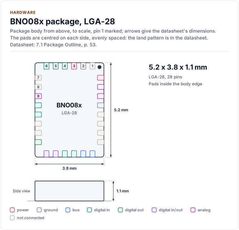
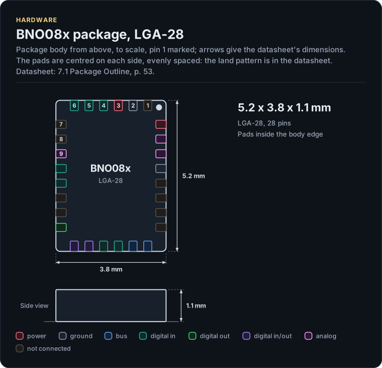
Figure description and sources
The BNO08x package seen from the top and, when the height is known, from the side, drawn to scale: 5.2 x 3.8 x 1.1 mm. The arrows carry the datasheet's dimensions, the dot marks pin 1 and the pads are numbered counter-clockwise from it, coloured by the pin's electrical type (legend below). Pads sit centred on each side, evenly spaced; the datasheet's land pattern is the reference for a board.
Drawn from: docs/hardware.yml; inc/bno08x_interface.hpp.
Hardware description: docs/hardware.yml
Drawn from:
BNO08x pinout, LGA-28
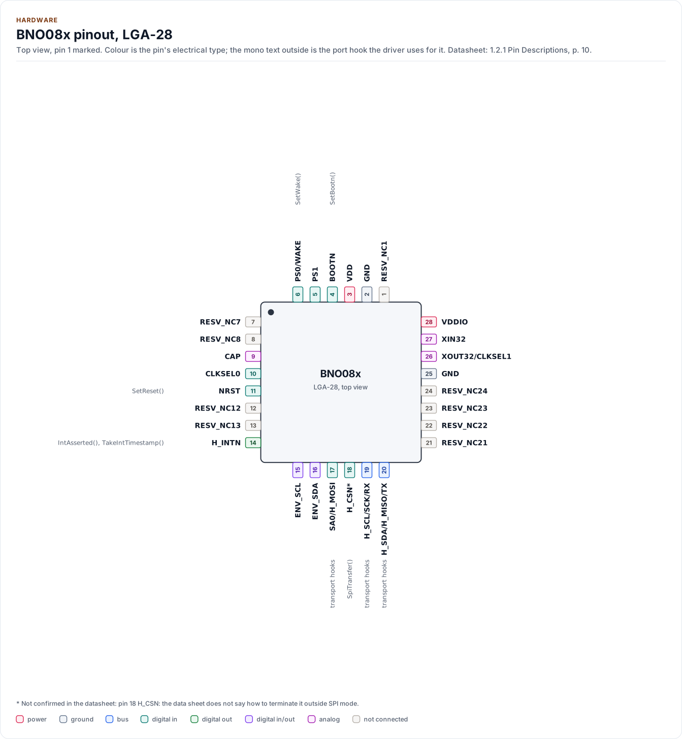
Figure description and sources
The BNO08x seen from the top, in its LGA-28 package. Pin 1 is marked by the dot; the numbers run counter-clockwise from it. Each pad is coloured by the pin's electrical type (legend below). Next to it is the pin's name and, in mono, the hook of the driver's port that drives or reads it; a pin without a hook is not used by the driver.
Drawn from: docs/hardware.yml; inc/bno08x_interface.hpp.
Hardware description: docs/hardware.yml
Drawn from:
The layers, one of them yours
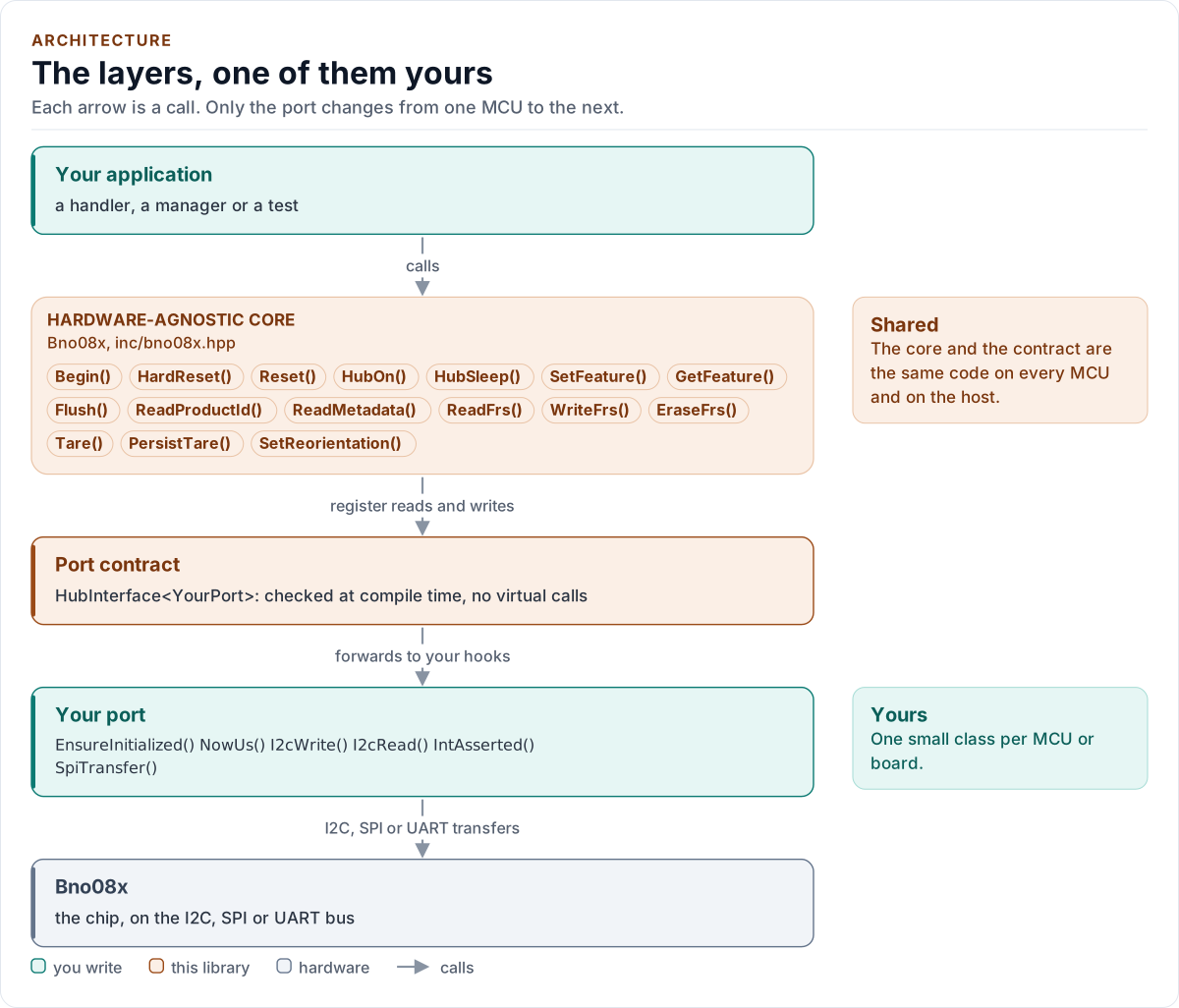
Figure description and sources
Top to bottom, each arrow is a call. Your application calls one object, whose public calls are listed from the umbrella header in inc/. The core turns each call into register reads and writes and hands them to the port contract (the CRTP base in inc/*_interface.hpp), which forwards them, at compile time, to the hooks of the port class you write; your port moves the bytes on the bus. The notes on the right say which layers stay the same on every MCU and which one you write. A library without a port contract has only the first two layers.
Drawn from: inc/bno08x.hpp public calls; inc/bno08x_interface.hpp HubInterface; figure module docs/diagrams/figures/driver-layers.py.
Figure module: docs/diagrams/figures/driver-layers.py
Drawn from:
public callsininc/bno08x.hppHubInterfaceininc/bno08x_interface.hpp
One sample through the layers
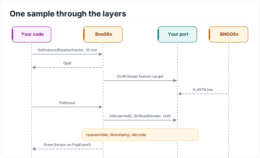
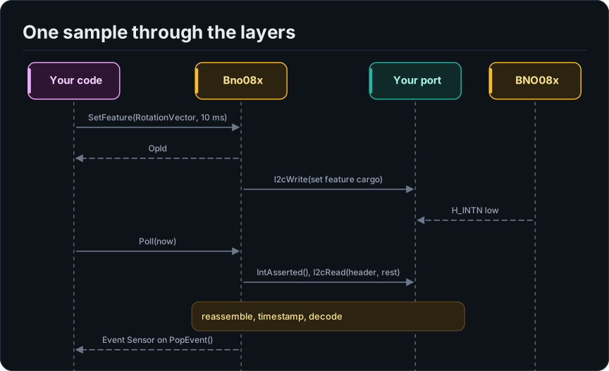
Figure description and sources
Participants, left to right: Your code, Bno08x, Your port and BNO08x. The steps run from top to bottom. Your code sends SetFeature(RotationVector, 10 ms) to Bno08x. Bno08x returns OpId to Your code. Bno08x sends I2cWrite(set feature cargo) to Your port. BNO08x returns H_INTN low to Your port. Your code sends Poll(now) to Bno08x. Bno08x sends IntAsserted(), I2cRead(header, rest) to Your port. A note over Bno08x says: reassemble, timestamp, decode. Bno08x returns Event Sensor on PopEvent() to Your code.
Drawn from: docs/model/one-sample-through-the-layers.seq.yml.
Hardware description: docs/model/one-sample-through-the-layers.seq.yml
Drawn from:
Session states of the driver
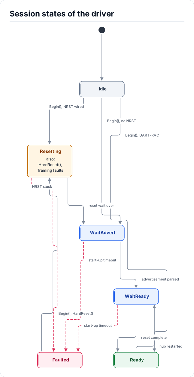
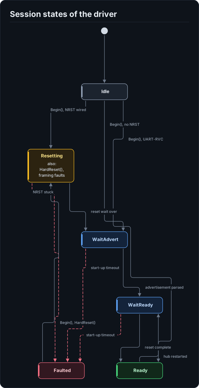
Figure description and sources
Six states. The session starts in Idle. Begin() leaves Idle for Resetting when NRST is wired, for WaitAdvert when it is not, and for Ready on UART-RVC. Resetting goes to WaitAdvert when the reset wait is over. WaitAdvert goes to WaitReady once the advertisement is parsed, and WaitReady goes to Ready when the reset is complete. Ready goes back to WaitReady when the hub restarts. Resetting is also entered by HardReset() and by framing faults. Faulted is reached from Resetting when NRST cannot be released and from WaitAdvert or WaitReady on a start-up timeout, and Begin() or HardReset() lead from Faulted back to Resetting.
Drawn from: docs/model/session-states.state.yml.
Hardware description: docs/model/session-states.state.yml
Drawn from: