Architecture
How the driver is built: three layers, one of them yours, and what happens in each when you take a measurement.
Datasheet sections this page relies on
From Bosch Sensortec BST-BMP581-DS004-13 1.13:
- Supplies, timing and conversion times: 2 Specification; Table 4 Electrical characteristics, p. 10
- Register writes only in standby: 4.3.8 Mode-depending register write restrictions, p. 18
- Post-power-up checks: 4.3.9 Post-power-up procedure, p. 18
- Soft reset: 4.3.10 Soft reset; 7.36 Register (0x7E) Command Register, p. 18
- Data registers and data shadowing: 4.5 Data registers; 4.5.1 Data Shadowing, p. 22
- Read burst address increment: 5.4 Read burst address increment, p. 36
All of them, with the driver API for each: Datasheet map.
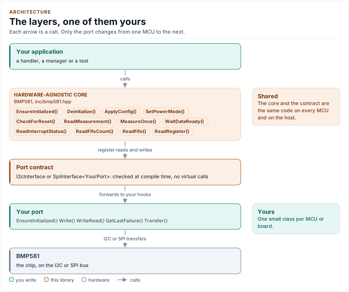
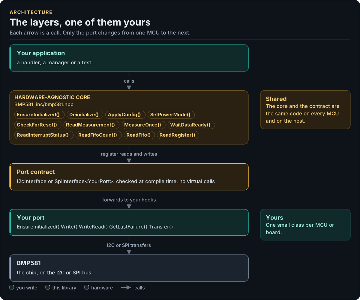
Figure description and sources
Top to bottom, each arrow is a call. Your application calls one object, whose public calls are listed from the umbrella header in inc/. The core turns each call into register reads and writes and hands them to the port contract (the CRTP base in inc/*_interface.hpp), which forwards them, at compile time, to the hooks of the port class you write; your port moves the bytes on the bus. The notes on the right say which layers stay the same on every MCU and which one you write. A library without a port contract has only the first two layers.
Drawn from: inc/bmp581.hpp public calls; inc/bmp581_i2c_interface.hpp I2cInterface; inc/bmp581_spi_interface.hpp SpiInterface; figure module docs/diagrams/figures/driver-layers.py.
Layers
| Layer | Files | Owns |
|---|---|---|
| Core | inc/bmp581.hpp, src/bmp581.ipp |
Lifecycle, configuration, power modes, measurements, the FIFO, the reset check, errors |
| Types and registers | inc/bmp581_types.hpp, inc/bmp581_registers.hpp |
Error, Result<T>, Config and presets, timing and range constants, the conversions; the register map |
| Port contracts | inc/bmp581_i2c_interface.hpp, inc/bmp581_spi_interface.hpp |
Each bus's CRTP base, its concept (I2cPort, SpiPort), its bus requirements and its register framing |
| Platform port | Your class | Bus bring-up and byte transfers, delays, optionally the failure reason (I2C) and logging |
| Kconfig layer | inc/bmp581_kconfig.hpp |
Optional: a Config from ESP-IDF menuconfig |
Two buses, one driver
The register model is the same on both buses; only the framing differs (sections 5.5, 5.6):
| I2C | SPI | |
|---|---|---|
| Read | WriteRead(): the address, then the data |
One frame: address with bit 7 set, then the data |
| Write | Write(): address and one data byte |
One frame: address with bit 7 clear, one data byte |
| Start-up | Nothing extra | A dummy read selects SPI, again after each soft reset (section 5.1) |
| Soft reset | NACKed by the chip, expected (section 7.36) | A normal frame |
| Address NACK | NoDevice with GetLastFailure() |
No ACK on SPI: an absent chip reads as a stuck line |
BMP581<Port> takes either: the BusPort concept accepts a class that is exactly one of I2cPort and SpiPort,
and detail::BusFor<Port> picks I2cRegisterBus or SpiRegisterBus at compile time. Both framings expose the
same four operations (select the interface, read a burst, write one register, write the reset command), so the core
has no bus-specific code. Every write is one register in one transfer: the chip stores it whole or not at all, and
SPI would need an address per byte in a burst anyway (figure 9).
One measurement through the layers
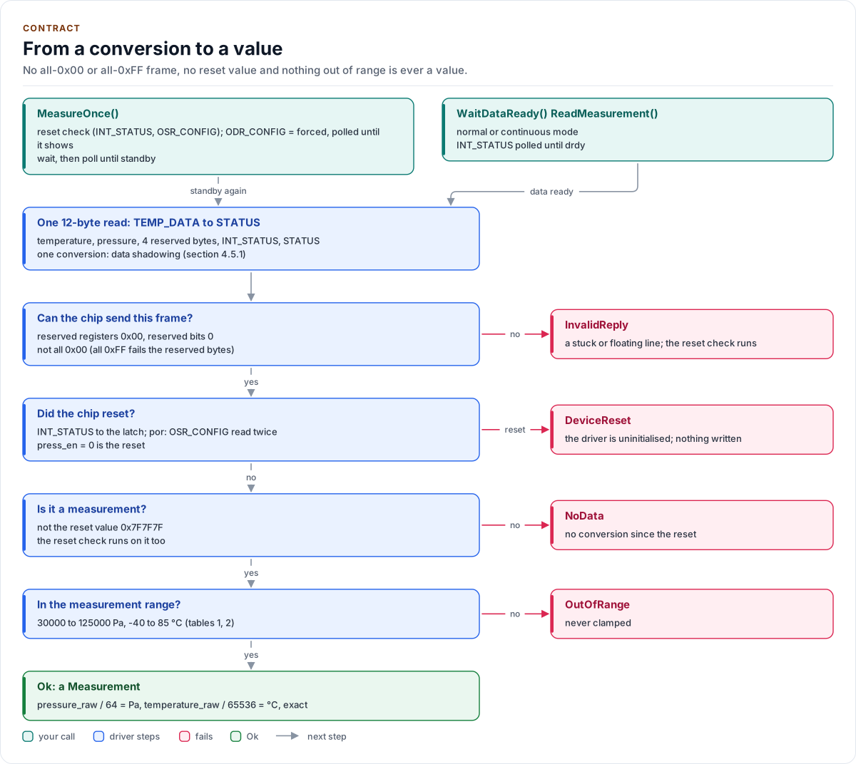
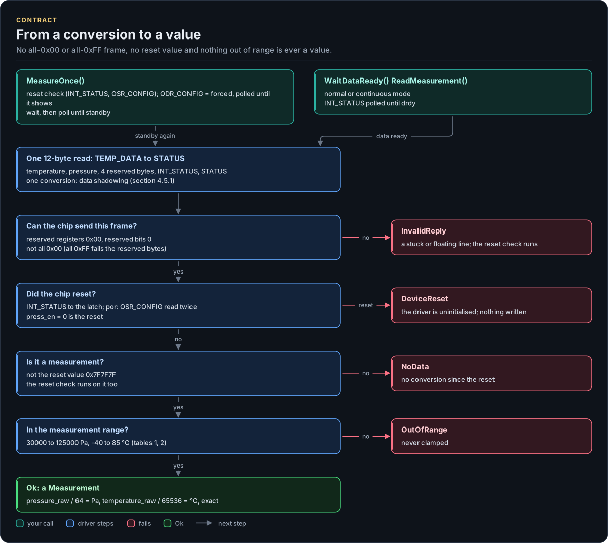
Figure description and sources
Two entry points at the top. MeasureOnce() runs the reset check (INT_STATUS, then OSR_CONFIG to OSR_EFF in one read), writes ODR_CONFIG with pwr_mode = forced, polls it until it shows forced (at most t_startup) to prove the measurement started, waits the typical conversion time less 5 percent, then polls the same registers until the chip is back in standby, at most the datasheet maximum. In normal or continuous mode, WaitDataReady() polls INT_STATUS until drdy. Both end in the same read: one 12-byte burst of TEMP_DATA to STATUS, so temperature and pressure come from one conversion (data shadowing). The checks below run in order, and each failure has its error card on the right: the reserved registers must read 0x00 and the frame must not be all 0x00 (a stuck or floating line); INT_STATUS goes to the latch, and a por in it runs the reset check; the reset value 0x7F7F7F is no measurement and runs the reset check too; the values must lie in the measurement range. Only then is the value returned, in 1/64 Pa and 1/65536 degrees Celsius.
Drawn from: src/bmp581.ipp MeasureOnce, waitForcedShown, WaitDataReady, readData, settle; inc/bmp581_registers.hpp kDataReset; inc/bmp581_types.hpp kPressureMinPa, kPressureMaxPa, kTemperatureMinC, kTemperatureMaxC; figure module docs/diagrams/figures/measurement.py.
sequenceDiagram
    participant App as Your code
    participant Core as BMP581<Port>
    participant Port as Your port
    App->>Core: MeasureOnce()
    Core->>Port: read OSR_CONFIG, ODR_CONFIG
    Port-->>Core: press_en = 1, standby
    Core->>Port: write ODR_CONFIG: forced
    Core->>Port: read OSR_CONFIG, ODR_CONFIG (forced: started)
    Note over Core: wait the conversion, poll until standby
    Core->>Port: read TEMP_DATA..STATUS (12 bytes)
    Port-->>Core: data, reserved 0x00, INT_STATUS, STATUS
    Note over Core: line, reset, reset value and range checks
Core-->>App: Result<Measurement>{Ok}Start-up
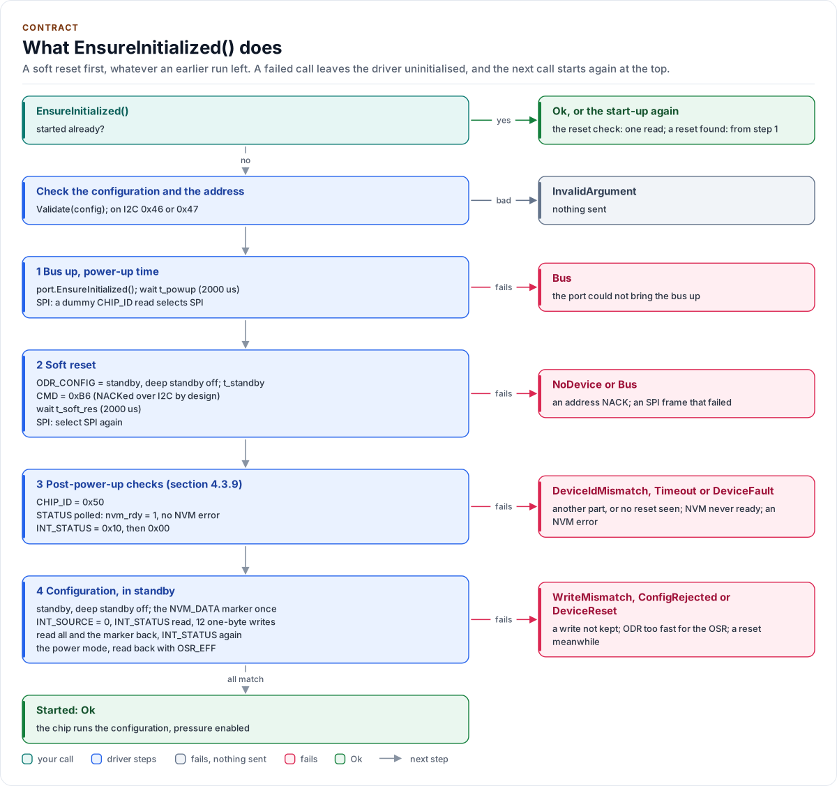
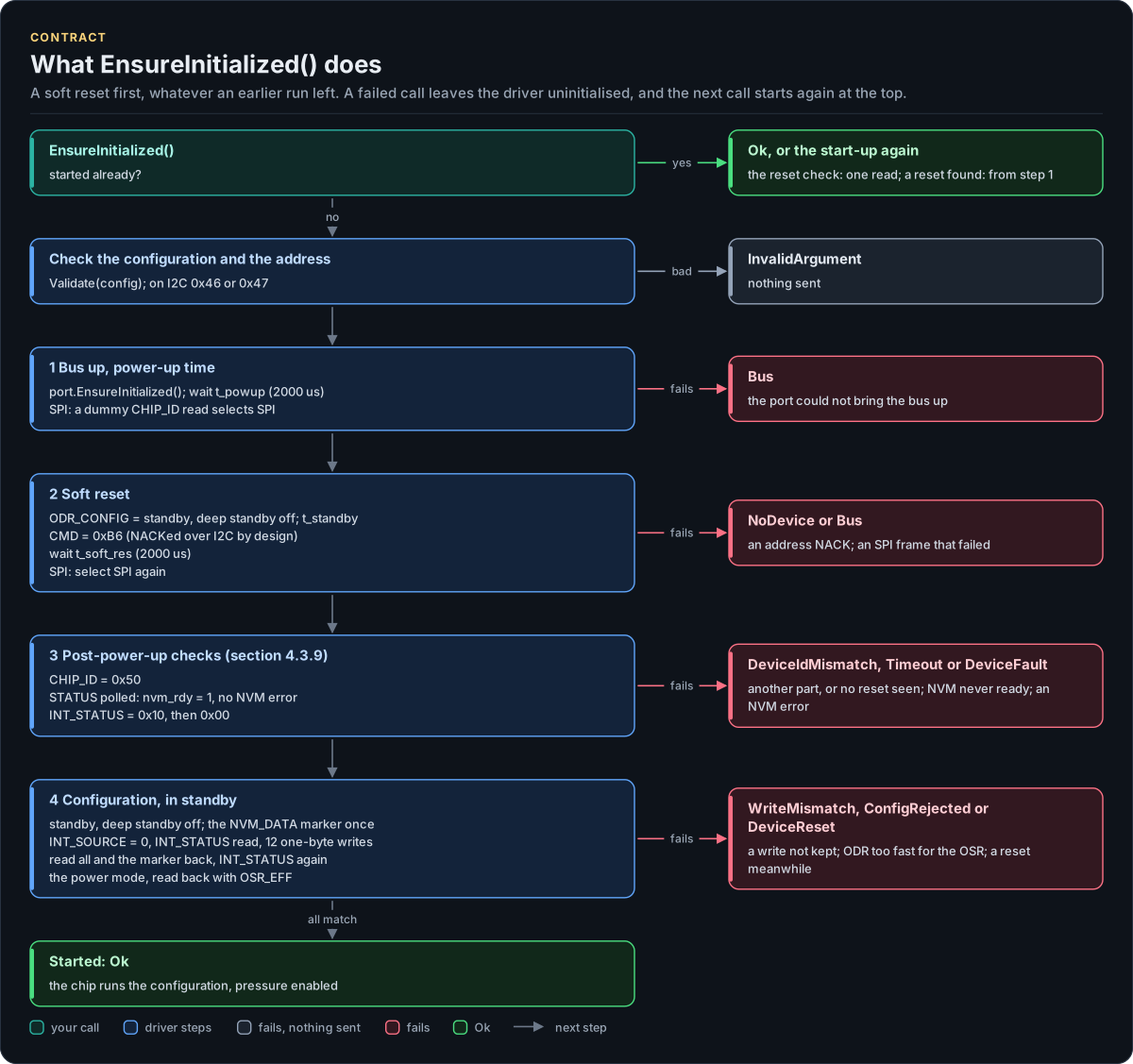
Figure description and sources
Top to bottom on the left, the steps of the first EnsureInitialized() call; once it has succeeded a later call runs the reset check (one 3-byte read of OSR_CONFIG to OSR_EFF) and returns Ok, or starts again at the top when the chip reset. The configuration and the I2C address are checked before any I/O. Step 1 waits the power-up time and, on SPI, sends the dummy read that changes the chip from I2C to SPI. Step 2 is the soft reset: standby with deep standby off first (the datasheet does not say that deep standby takes CMD), then CMD = 0xB6, which the chip does not acknowledge over I2C, then the soft reset time, and on SPI the selection read again, since a reset returns the interface to I2C. Step 3 is the datasheet's post-power-up check: CHIP_ID, STATUS polled until the NVM is ready with no error, and INT_STATUS, which must read 0x10 (the reset happened) and then 0x00 (the read cleared it), a check no stuck, floating or looped-back line can pass. Step 4 leaves the deep standby the reset left the chip in (standby with deep standby off, then t_standby), writes the marker to NVM_DATA once, writes the configuration one register per transfer with ODR_CONFIG last, reads all of it and the marker back, reads INT_STATUS once more, and enters the configured power mode, read back too. Each card on the right is the error a step returns; after any failure the driver stays uninitialised and the next call starts at the top.
Drawn from: src/bmp581.ipp EnsureInitialized, initialize, resetChip, identify, waitNvmReady, checkResetFlags, configure; inc/bmp581_registers.hpp kChipIdValue, kIntStatusAfterReset, kCmdSoftReset; inc/bmp581_types.hpp kPowerUpUs, kSoftResetUs; figure module docs/diagrams/figures/start-up.py.
Design choices
- CRTP, not virtual functions. The port is a template parameter constrained by a concept, so every call is resolved at compile time and a missing hook is a compile error that names it.
- Optional hooks by named concepts.
DelayUs,GetLastFailureandLogare detected byDeclares*andHas*concepts inbmp581::detail. A missingDelayUs()fails to compile, a missingGetLastFailure()reports every failure asBus, a missingLog()logs nothing; a misdeclared hook is a compile error. - No I/O in the constructor. Construction cannot fail, so the driver can be a static or a member of a handler.
- One error type.
Result<T>carries a value and anError; nothing throws and nothing returns a barebool. - One read buffer, owned by the driver. Every read lands in the driver object's 96-byte buffer, and the SPI framing keeps its frames in the framing object, so the bus and its DMA never see a caller's stack. A value is copied out of the buffer before any later read (the reset check) reuses it.
- No heap, no exceptions, no RTTI, no
std::function, noprintf. The driver is a header-only template with no mutable static state.
Source map
| You want | Read |
|---|---|
| The public API | inc/bmp581.hpp |
| How a call is implemented | src/bmp581.ipp |
| Register addresses and bits | inc/bmp581_registers.hpp |
| The port contracts | inc/bmp581_i2c_interface.hpp, inc/bmp581_spi_interface.hpp |
Next: Contract.