Architecture
How the driver is built: three layers, one of them yours, and what happens in each when you read or write.
Datasheet sections this page relies on
From Microchip (Atmel) Atmel-8707 F:
- Instruction set and A8 in the opcode: 6 Functional Description, Table 6-1, p. 8
- Sequential read and roll-over: 6 Functional Description, Read Sequence (READ), p. 9
- Page write, the page wrap and the self-timed write cycle: 6 Functional Description, Write Sequence (WRITE), p. 9
All of them, with the driver API for each: Datasheet map.
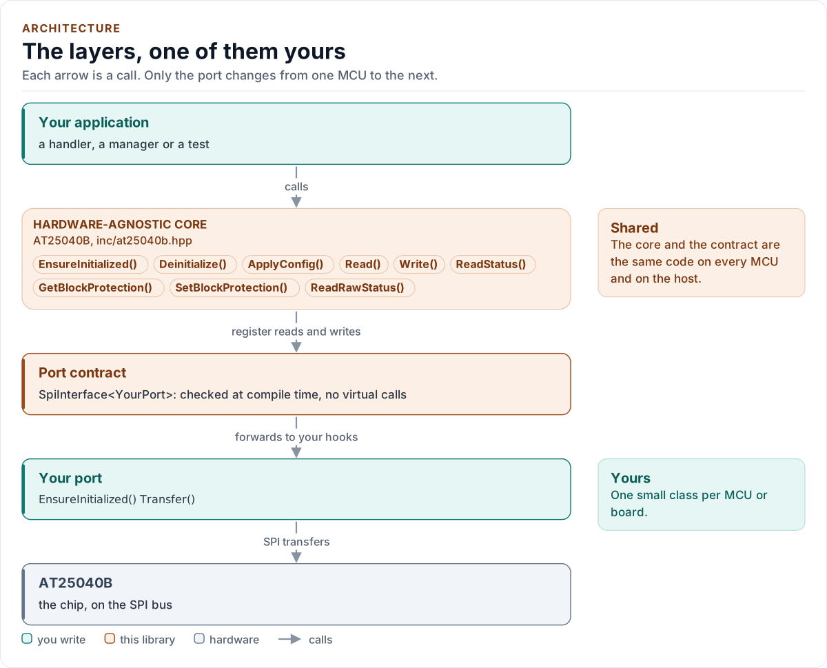
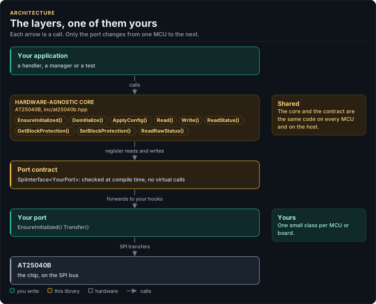
Figure description and sources
Top to bottom, each arrow is a call. Your application calls one object, whose public calls are listed from the umbrella header in inc/. The core turns each call into register reads and writes and hands them to the port contract (the CRTP base in inc/*_interface.hpp), which forwards them, at compile time, to the hooks of the port class you write; your port moves the bytes on the bus. The notes on the right say which layers stay the same on every MCU and which one you write. A library without a port contract has only the first two layers.
Drawn from: inc/at25040b.hpp public calls; inc/at25040b_spi_interface.hpp SpiInterface; figure module docs/diagrams/figures/driver-layers.py.
Layers
| Layer | Files | Owns |
|---|---|---|
| Core | inc/at25040b.hpp, src/at25040b.ipp |
Lifecycle, identity check, range checks, page split, write cycle waits, WP handling, verification, errors |
| Types and registers | inc/at25040b_types.hpp, inc/at25040b_registers.hpp |
Error, Result<T>, Variant, BlockProtect, Status, Config; the opcodes and status bits |
| Port contract | inc/at25040b_spi_interface.hpp |
The bus requirements, the CRTP base, CtrlPin and GpioSignal, the SpiPort concept, detail::EepromBus (one transfer per instruction, A8 in the opcode, the transfer buffers) |
| Compile-time helpers | inc/at25040b_detail.hpp |
Exact hook probes, Field<> for BP1:BP0, enumerator checks; no run-time code |
| Platform port | Your class | Bus bring-up, transfers and delays; optionally the WP pin and logging |
| Kconfig layer | inc/at25040b_kconfig.hpp |
Optional: a Config from ESP-IDF menuconfig |
One read through the layers
sequenceDiagram
    participant App as Your code
    participant Core as AT25040B<Port>
    participant Port as Your port
    App->>Core: Read(0x1F0, buf) (16 bytes)
    Core->>Port: Transfer(RDSR)
    Port-->>Core: true, status 0x00
    Core->>Port: Transfer(RDSR)
    Port-->>Core: true, status 0x00 (confirmed idle)
    Core->>Port: Transfer(READ 0x0B, 0xF0, 16 bytes)
    Port-->>Core: true, 16 bytes
    Core-->>App: Result<void>{Ok}
A longer read sends one READ every 16 bytes, recomputing A8 for each; Read(..., Verify::ReadBack) sends each READ
twice and compares. A write is drawn on the
API guide.
Design choices
- CRTP, not virtual functions. The port is a template parameter constrained by the
SpiPortconcept, so every call is resolved at compile time and a missing hook is a compile error that names it. - Optional hooks by named concepts.
GpioSetandLogare detected byHas*concepts in one place, with their exact types andnoexcept; a hook that is declared with another signature is a compile error. A missingDelayUs()fails to compile, a missingGpioSet()leaves WP to the board, a missingLog()logs nothing. - Spans, bounded at the bus helper.
Read()andWrite()takestd::span; the bus helper checks every length against its buffer before anything is sent (at compile time for a fixed extent), so no caller can overrun it. - No I/O in the constructor. Construction cannot fail and clocks nothing, so the driver can be a static or a member of a handler built at boot, before the module is plugged in.
- Check the bus, not only the chip. The chip has no ID register and its idle status, 0x00, is also what a dead bus reads. So the start-up check uses behaviour a dead bus cannot fake (the write enable latch), status reads are confirmed, reads are read twice and writes read back.
- Wait inside the call. A write returns after its last write cycle, so the next call finds the chip ready and a handler holding a lock knows when the bus is free.
- One error type.
Result<T>carries a value and anError; nothing throws and nothing returns a barebool. - No heap, no exceptions, no RTTI, no
std::function, noprintf. The driver is a header-only template with no mutable static state.
Transfer buffers and the read chunk
The port sees only the driver's two transfer buffers, tx_ and rx_ of detail::EepromBus: members of the driver
object, so they live where the object lives (place it in DMA-capable memory if the port uses DMA), never on a caller's
stack. Their size, kMaxTransferBytes = 18, is set by the read chunk, kReadChunkBytes = 16. The datasheet sets no
limit on a READ, so 16 is a design choice:
| Chunk | Buffers in the object | Longest CS-low time at 5 MHz | Command overhead |
|---|---|---|---|
| 8 | 20 bytes | 16 µs | 20 % |
| 16 | 36 bytes | 29 µs | 11 % |
| 32 | 68 bytes | 54 µs | 6 % |
| 512 (whole array) | 1028 bytes | 822 µs | 0.4 % |
16 keeps the buffers small, never holds a shared bus for long, is two whole pages (so a page read back is one READ)
and costs little bus time. It is a compile-time constant, not a Config value: the buffers are sized from it and no
value of it changes what the chip does.
Source map
| You want | Read |
|---|---|
| The public API | inc/at25040b.hpp |
| How a call is implemented | src/at25040b.ipp |
| Opcodes and status bits | inc/at25040b_registers.hpp |
| The port contract and the instruction framing | inc/at25040b_spi_interface.hpp |
Next: Contract.