Architecture
How the driver is built: three layers, one of them yours, and what happens in each when you read a frame.
Datasheet sections this page relies on
From Texas Instruments SBASB22 -:
- Data interface: lanes, word length and channel modes: 7.3.14 Data Interface; 7.3.14.1 ADC Channel Modes, Table 7-12, p. 42
- Register write and read frames: 7.5 Programming; 7.5.1 Register Write Operation; 7.5.2 Register Read Operation, p. 50
- Initialization example, single lane on SDOUT: 7.5.3 Initialization Example - Single Lane Mode on SDOUT, p. 51
- Common registers: 8.1 ADS93xx Common Registers, p. 53
- Channel registers AIN1 to AIN8: 8.2 AIN1 - AIN8 Channel Registers, p. 64
- Channel registers AIN9 to AIN16 (reversed order): 8.3 AIN9 - AIN16 Channel Registers, p. 86
All of them, with the driver API for each: Datasheet map.
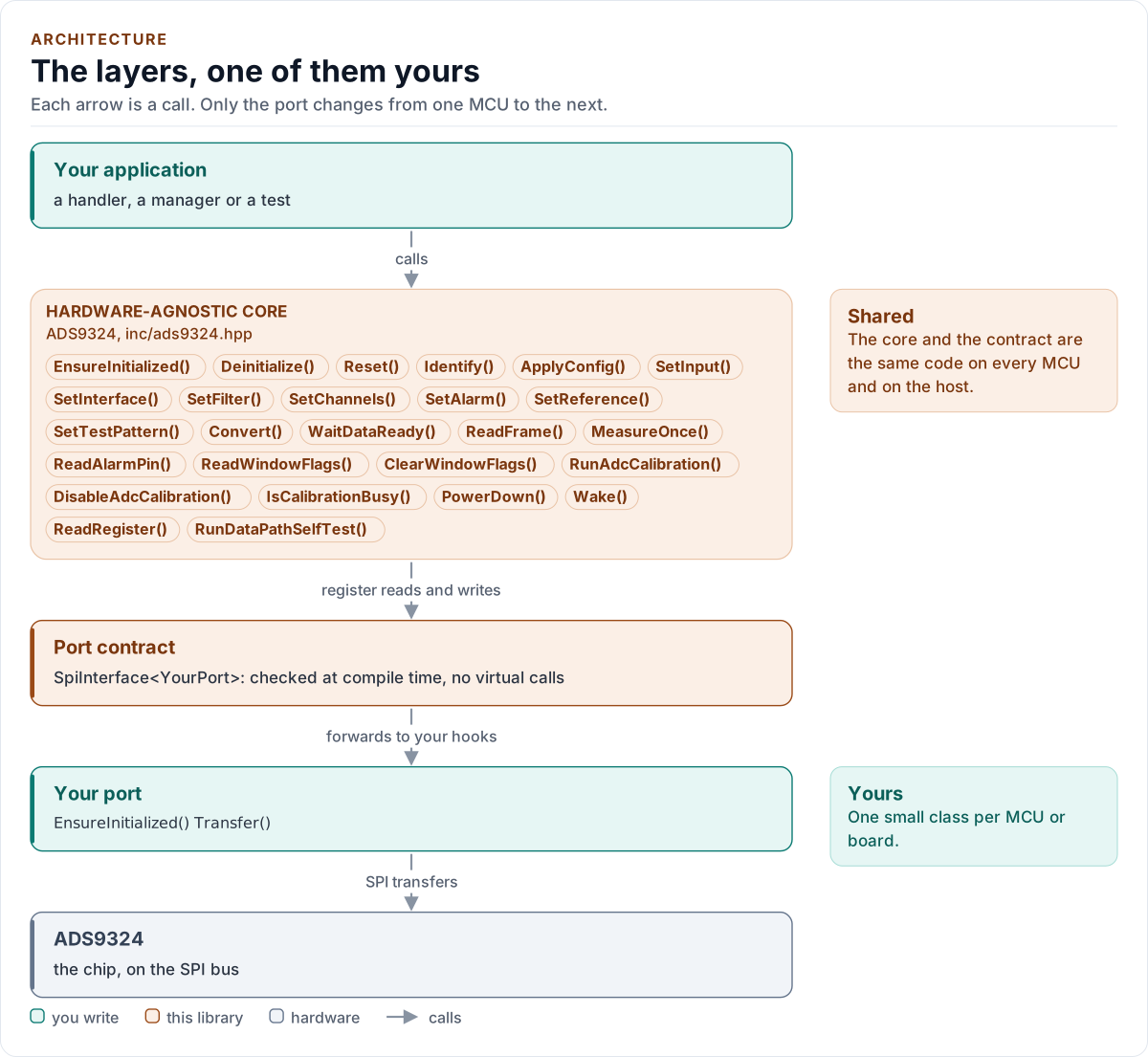
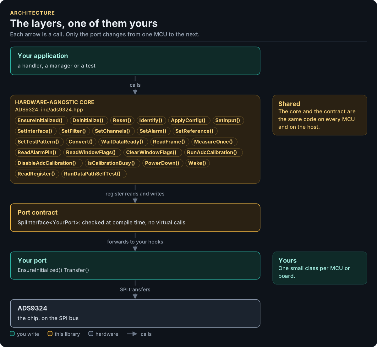
Figure description and sources
Top to bottom, each arrow is a call. Your application calls one object, whose public calls are listed from the umbrella header in inc/. The core turns each call into register reads and writes and hands them to the port contract (the CRTP base in inc/*_interface.hpp), which forwards them, at compile time, to the hooks of the port class you write; your port moves the bytes on the bus. The notes on the right say which layers stay the same on every MCU and which one you write. A library without a port contract has only the first two layers.
Drawn from: inc/ads9324.hpp public calls; inc/ads9324_spi_interface.hpp SpiInterface; figure module docs/diagrams/figures/driver-layers.py.
Layers
| Layer | Files | Owns |
|---|---|---|
| Core | inc/ads9324.hpp, src/ads9324.ipp |
Lifecycle, setters, conversions, calibration, standby, errors |
| Types and encoding | inc/ads9324_types.hpp, inc/ads9324_encode.hpp |
Error, Result<T>, Config and Validate(); the pure, constexpr Encode() of a Config into registers; the frame decoder |
| Registers | inc/ads9324_registers.hpp |
The three banks, 116 registers, fields, reset values, the channel-to-register mapping |
| Port contract | inc/ads9324_spi_interface.hpp |
The CRTP base, CtrlPin and GpioSignal, the SpiPort concept, the 24-bit register framing |
| Platform port | Your class | Bus bring-up and frame transfers, optionally delays, the CONVST, RESET and DRDY pins, lane capture and logging |
| Kconfig layer | inc/ads9324_kconfig.hpp |
Optional: a Config from ESP-IDF menuconfig |
The three register banks
The chip has a common bank (18 registers) and one bank per group of eight channels (49 registers each), selected
by BANK_SEL. The AIN9 to AIN16 bank is laid out in reverse order: bank-local index 15 - channel, so AIN16 is
local index 0 (the low byte of the first two-channel register), where the AIN1 to AIN8 bank puts AIN1 first. The
driver keeps one function, reg::Locate(channel), that returns the bank and the local index; every register
layout rule (the low half of a two-channel register belongs to the even local index) is written once on local
indexes. A host test programs every channel with a distinct value and checks the model's registers channel by
channel, and the data-path self-test proves the same on the data side.
Writing the configuration
detail::Encode(Config) is a pure function from a Config to a RegisterImage: the register values plus a mask of the
registers it touches. ApplyConfig() and every setter encode the new configuration, compare it with the shadow
(the register values the driver believes the chip holds) and write only what differs, in this order: the window
thresholds before DWC_EN, the filter registers, and a SYSREF pulse (CONVST 0, 1, 0) after the filter write, as the
datasheet requires. The shadow is updated after each accepted write, and the stored Config only when the whole
call succeeded. With Verify::ReadBack each written register is read back and compared.
One call through the layers
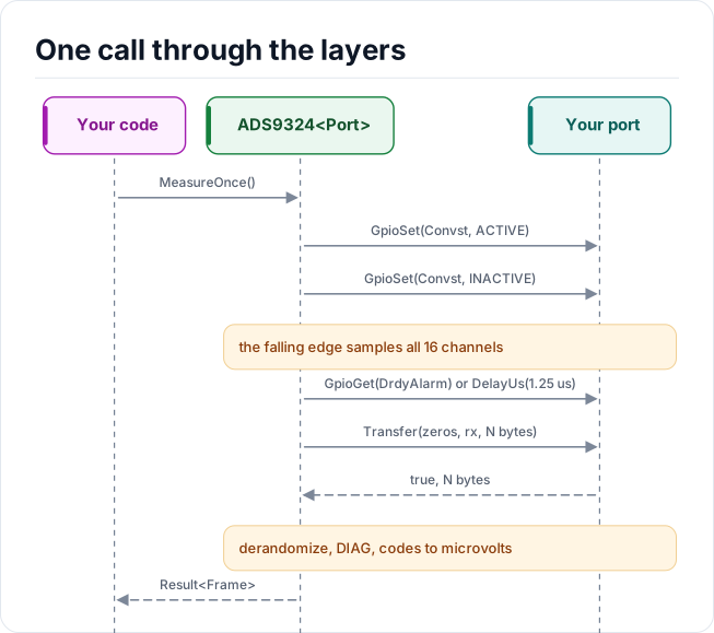
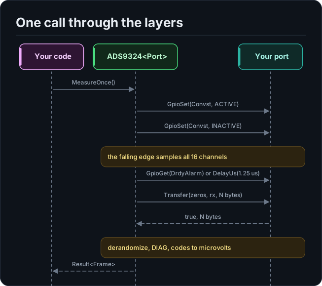
Figure description and sources
Participants, left to right: Your code, ADS9324
Drawn from: docs/model/one-call-through-the-layers.seq.yml.
Design choices
- CRTP, not virtual functions. The port is a template parameter constrained by the
SpiPortconcept, so every call is resolved at compile time and a missing hook is a compile error that names it. - Optional hooks by named concepts.
GpioSet,GpioGet,CaptureLanes,DelayUsandLogare detected withDeclares*andHas*concepts inads9324::detail. A hook that is declared with a wrong signature is a compile error, never a silent fallback; a hook that is absent falls back in a documented way. - No I/O in the constructor. Construction cannot fail, so the driver can be a static or a member of a handler.
- One error type.
Result<T>carries a value and anError; nothing throws and nothing returns a barebool. - No heap, no exceptions, no RTTI, no floating point. The driver is a header-only template with no mutable static state; voltages are integer microvolts.
- A configuration is data.
Validate()andEncode()are constexpr, so a fixed board configuration can be proved valid, and its register image checked, at compile time (CheckedConfig). - The daisy chain is a seam, not a feature.
DaisyChainis inConfigso the layout is stable, andValidate()refuses it; see Limitations.
Source map
| You want | Read |
|---|---|
| The public API | inc/ads9324.hpp |
| How a call is implemented | src/ads9324.ipp |
| Register addresses, fields and the bank mapping | inc/ads9324_registers.hpp |
How a Config becomes registers and a frame becomes codes |
inc/ads9324_encode.hpp |
| The port contract | inc/ads9324_spi_interface.hpp |
Next: Contract.