Architecture
How the driver is built, so you can read the code, add a feature or port it.
Datasheet sections this page relies on
From Analog Devices (Trinamic) 19-101926 1:
- Application modes: Application Modes, p. 16
All of them, with the driver API for each: Datasheet map.
Layers
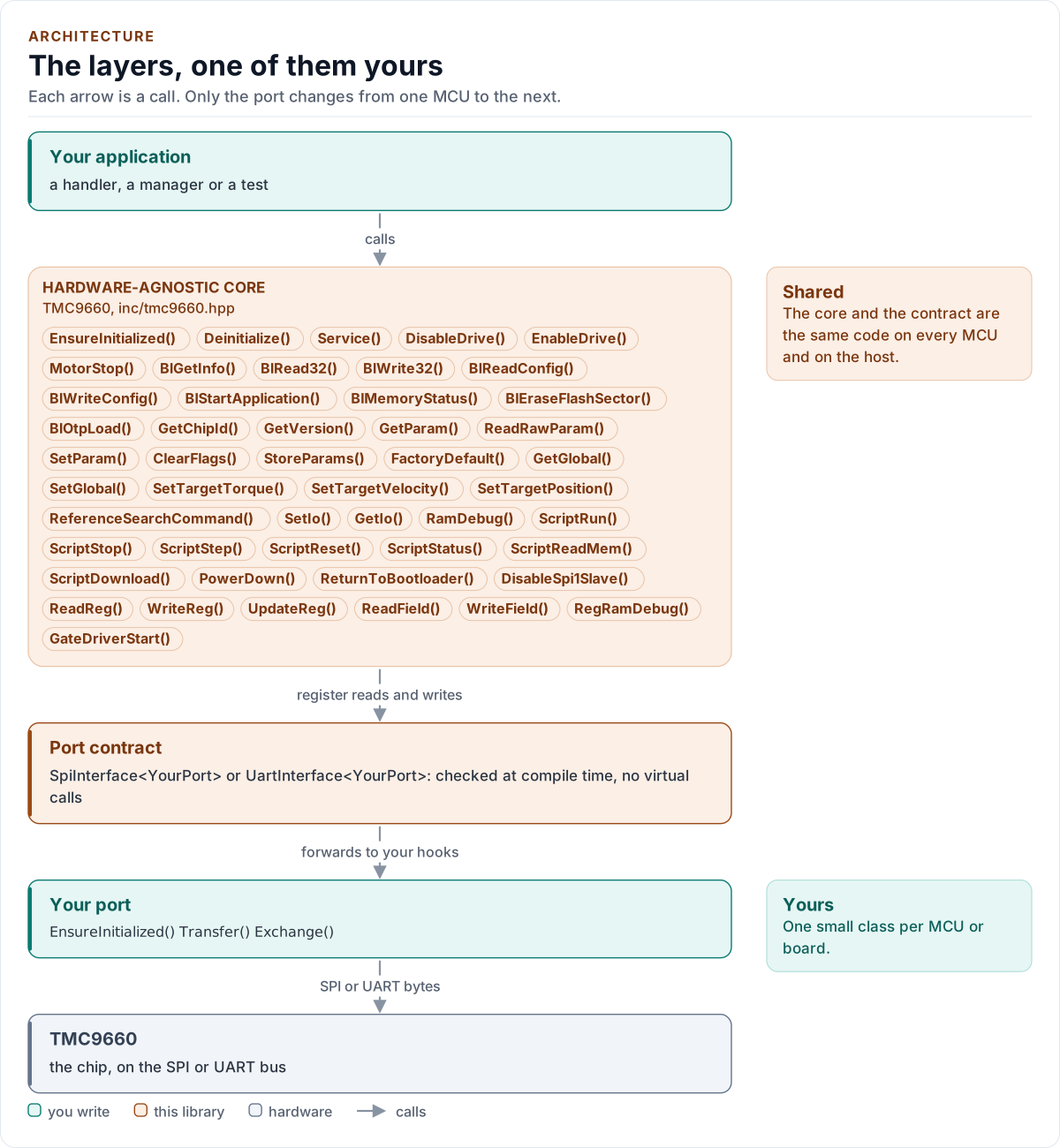
Figure description and sources
Top to bottom, each arrow is a call. Your application calls one object, whose public calls are listed from the umbrella header in inc/. The core turns each call into register reads and writes and hands them to the port contract (the CRTP base in inc/*_interface.hpp), which forwards them, at compile time, to the hooks of the port class you write; your port moves the bytes on the bus. The notes on the right say which layers stay the same on every MCU and which one you write. A library without a port contract has only the first two layers.
Drawn from: inc/tmc9660.hpp public calls; inc/tmc9660_spi_interface.hpp SpiInterface; inc/tmc9660_uart_interface.hpp UartInterface; figure module docs/diagrams/figures/driver-layers.py.
The core, tmc9660::TMC9660<Port>, has no platform code. It calls hooks on your port class, which derives from
SpiInterface<Port> or from UartInterface<Port>. The concept AnyPort accepts exactly one of the two, checked at
compile time.
Files
| File | Contents |
|---|---|
inc/tmc9660.hpp, src/tmc9660.ipp |
The class: lifecycle, the three modes, the safety guards |
inc/tmc9660_types.hpp |
Error, Result, Mode, Config, Quirks, enumerations |
inc/tmc9660_frames.hpp |
Pure frame encoders and decoders of all protocols, proved with static_assert |
inc/tmc9660_bootconfig.hpp |
BootConfig and the field table of the configuration memory |
inc/tmc9660_params.hpp |
The 289 parameters (generated) |
inc/tmc9660_registers.hpp |
The 163 registers and their bit fields (generated) |
inc/tmc9660_globals.hpp |
The global parameters of the four banks |
inc/tmc9660_spi_interface.hpp, inc/tmc9660_uart_interface.hpp |
The port contracts and the bus requirements |
inc/tmc9660_kconfig.hpp |
KconfigDefaults() for ESP-IDF menuconfig |
The .ipp file is included at the end of tmc9660.hpp: the driver is header-only.
One class, three modes
The chip speaks one of three protocols, and which one depends on its boot configuration, so the mode is a run-time
value (Mode), not a template parameter. Every public function starts with need(Mode): a call in the wrong mode
returns WrongMode before it touches the bus. A change of mode, by BlStartApplication(), BlWriteConfig() or
ReturnToBootloader(), updates mode_ after the chip identity has been read in the new mode.
Transport and protocol are separate
Frames are built and parsed by detail:: functions in tmc9660_frames.hpp: no I/O, no state, constexpr, each proved
against the documents' worked examples. The class owns the exchange: send the frame, check the reply, track the reset
evidence of that transport (FIRST_CMD, the boot bit and datagram counter, the canary), map the result to Error.
That is why a protocol detail is a unit test of a pure function and the exchange logic is a test against the chip
model.
Generated tables
The parameter and register tables are generated from tools/gen_tables/params.json and regs.json, which were
transcribed from the reference manuals, by tools/gen_tables/gen_tables.py. The output is formatted with the
repository's clang-format and a CTest checks that the committed headers equal the generator's output
(Testing).
The model
tests/mock_tmc9660.hpp is an independent model of the chip, written from the documents and not from the driver: it
has the three protocols, the parameter and register tables, memories, reset, and the faults of the chip as switches.
It records what happened to the chip (writes after a reset, energise events with an error flag latched or DRV_EN low,
boot with the drive on) so that a test asserts on the chip, not on the driver's own opinion.