Architecture
How the driver is built: three layers, one of them yours, and what happens inside the calls that matter most.
Datasheet sections this page relies on
From NXP PCA9685 Rev. 4:
- Control register: 7.2 Control register, p. 9
- Register summary and auto-increment: Table 4 Register summary, p. 10
- LED output and PWM control, full ON and full OFF: 7.3.3 LED output and PWM control; Table 7; Figure 9, p. 16
- I2C bus transactions: 9 Bus transactions; Figures 20 to 24, p. 32
All of them, with the driver API for each: Datasheet map.
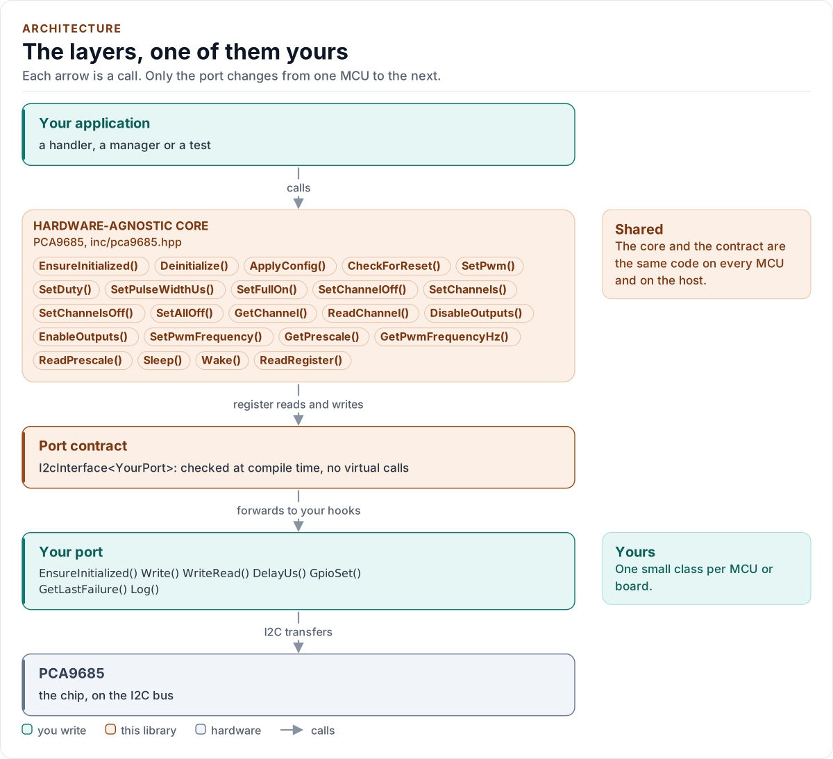
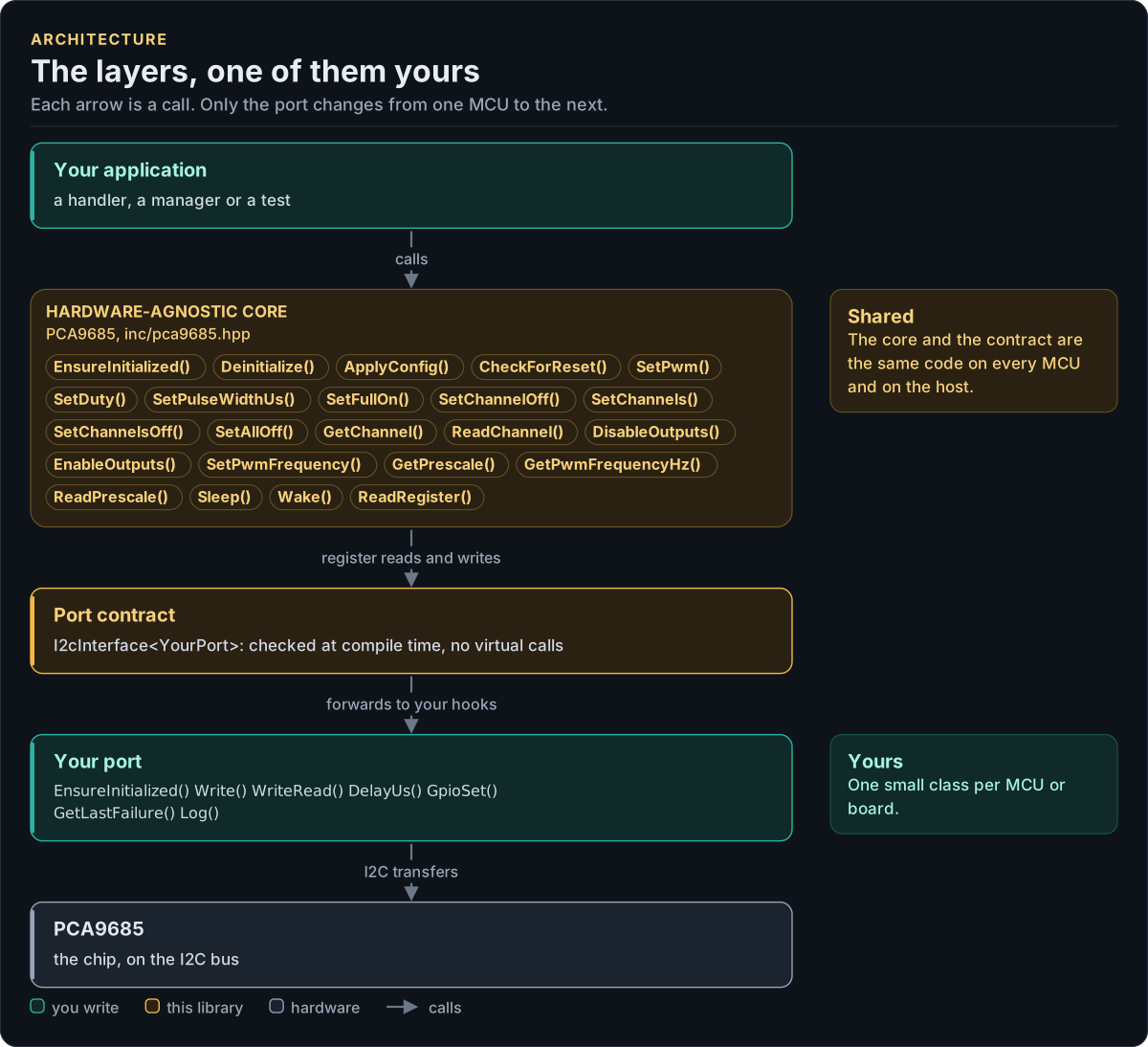
Figure description and sources
Top to bottom, each arrow is a call. Your application calls one object, whose public calls are listed from the umbrella header in inc/. The core turns each call into register reads and writes and hands them to the port contract (the CRTP base in inc/*_interface.hpp), which forwards them, at compile time, to the hooks of the port class you write; your port moves the bytes on the bus. The notes on the right say which layers stay the same on every MCU and which one you write. A library without a port contract has only the first two layers.
Drawn from: inc/pca9685.hpp public calls; inc/pca9685_i2c_interface.hpp I2cInterface; figure module docs/diagrams/figures/driver-layers.py.
Layers
| Layer | Files | Owns |
|---|---|---|
| Core | inc/pca9685.hpp, src/pca9685.ipp |
Lifecycle, channels, frequency, sleep and restart, reset detection, the copy and its doubts, errors |
| Types and registers | inc/pca9685_types.hpp, inc/pca9685_registers.hpp |
Error, Result<T>, Pwm, Config and presets, the frequency and pulse arithmetic; the register map |
| Port contract | inc/pca9685_i2c_interface.hpp |
The bus requirements, the CRTP base, CtrlPin and GpioSignal, the I2cPort concept, the optional hooks, the register framing |
| Platform port | Your class | Bus bring-up and byte transfers, the delay, optionally OE, the failure reason and logging |
| Kconfig layer | inc/pca9685_kconfig.hpp |
Optional: a Config from ESP-IDF menuconfig |
Start-up
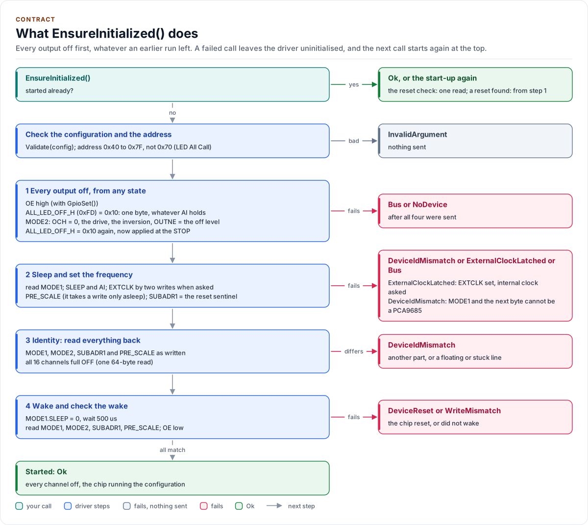
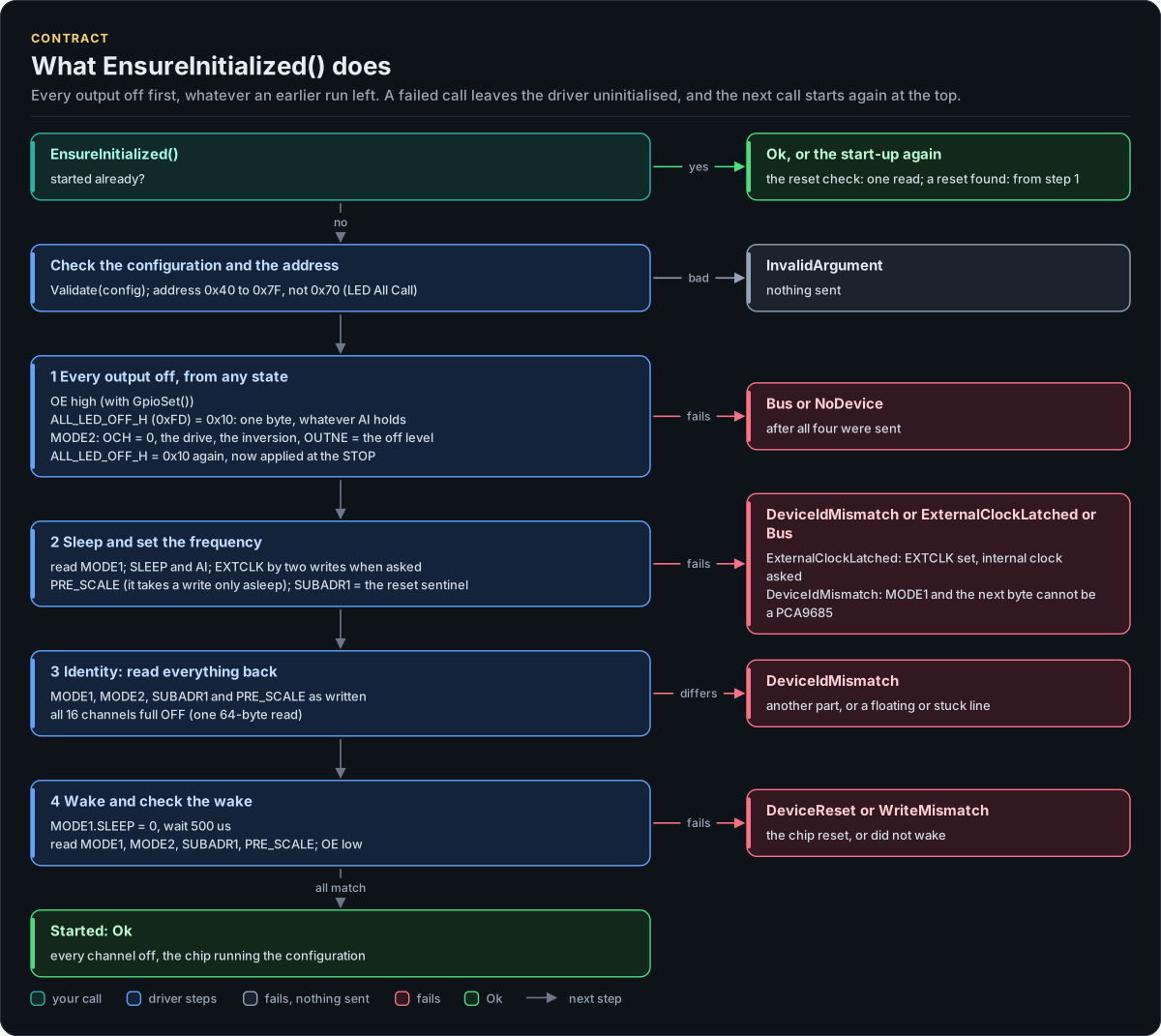
Figure description and sources
Top to bottom on the left, the steps of the first EnsureInitialized() call; once it has succeeded a later call runs the reset check (one read) and returns Ok, or starts again at the top when the chip reset. The configuration and the address are checked before any I/O. Step 1 switches everything off whatever an earlier run left: OE high, then one-byte ALL_LED_OFF_H writes before and after MODE2, which sets OCH = 0 so the second one reaches the outputs at its STOP; all four are sent even when one fails. Step 2 reads MODE1, puts the chip to sleep with auto-increment on (EXTCLK by the two-write sequence when asked), writes PRE_SCALE, which only takes a write asleep, and the SUBADR1 reset sentinel. Step 3 is the identity check: the chip has no ID register, so MODE1, MODE2, SUBADR1 and PRE_SCALE must read back what was written and every channel full OFF. Step 4 wakes the oscillator, waits its start-up, runs the wake check (MODE1, MODE2, SUBADR1 and PRE_SCALE once more) and enables OE. Each card on the right is the error a step returns; after any failure the driver stays uninitialised and the next call starts at the top.
Drawn from: src/pca9685.ipp EnsureInitialized, initialize, enterSafeState, configureClock, checkIdentity, wakeSequence, addressValid; inc/pca9685_types.hpp kMinI2cAddress, kMaxI2cAddress, kAllCallAddress, kOscillatorStartUs; inc/pca9685_registers.hpp kAllLedOffH, kLedFull; figure module docs/diagrams/figures/start-up.py.
One channel write
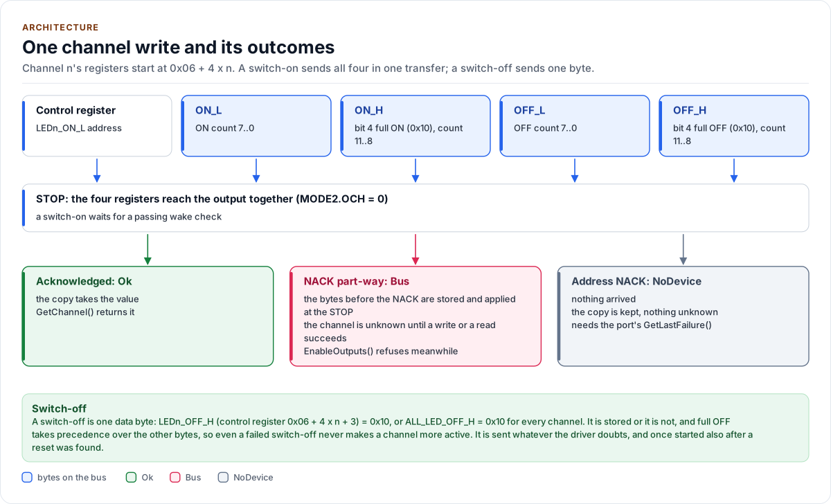
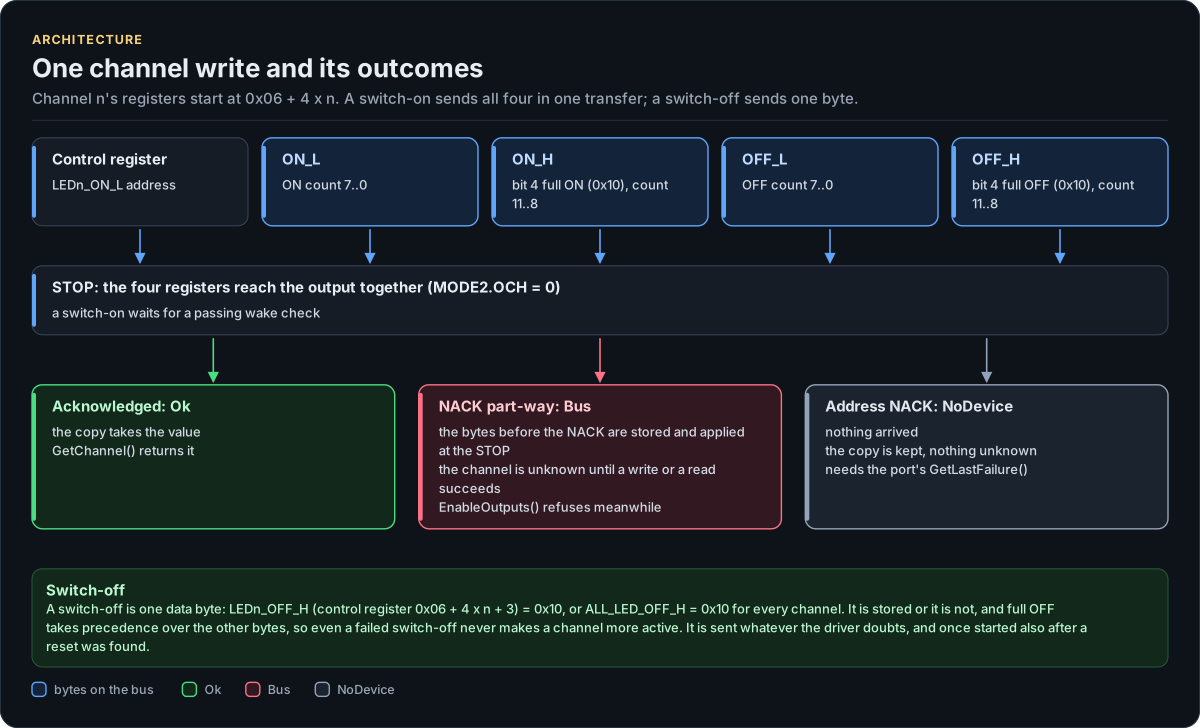
Figure description and sources
Top, the transfer the driver sends for a switch-on (SetDuty(), SetPulseWidthUs(), SetFullOn(), SetPwm()): the control register LEDn_ON_L, then ON_L, ON_H, OFF_L and OFF_H, with auto-increment. With MODE2.OCH = 0, which the driver always keeps, the bytes reach the output together at the STOP. Below, the outcomes: an acknowledged transfer updates the driver's copy; a NACK part-way leaves the bytes before it stored and applied at the STOP, so the channel may hold old, new or mixed values and becomes unknown; an address NACK proves nothing arrived. The band at the bottom is the switch-off: one data byte, LEDn_OFF_H = 0x10, stored or not, and full OFF takes precedence, so a switch-off never makes a channel more active, even when it fails; it is sent whatever the driver doubts.
Drawn from: src/pca9685.ipp applyOne, switchOn, switchOff, afterSwitchOff, writeChannels; inc/pca9685_registers.hpp kLed0OnL, kBytesPerChannel, kLedFull; figure module docs/diagrams/figures/channel-write.py.
Sleep, wake and restart
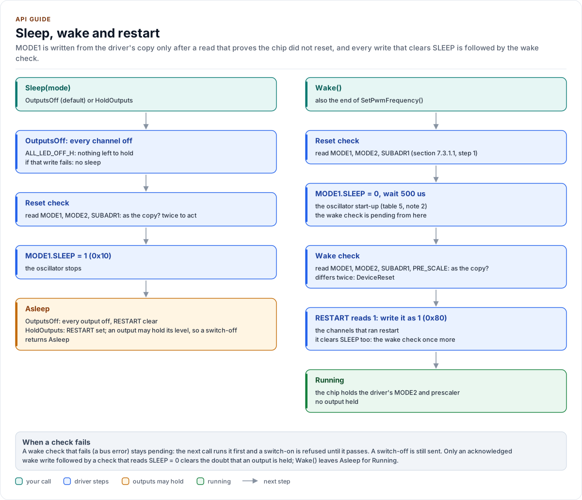
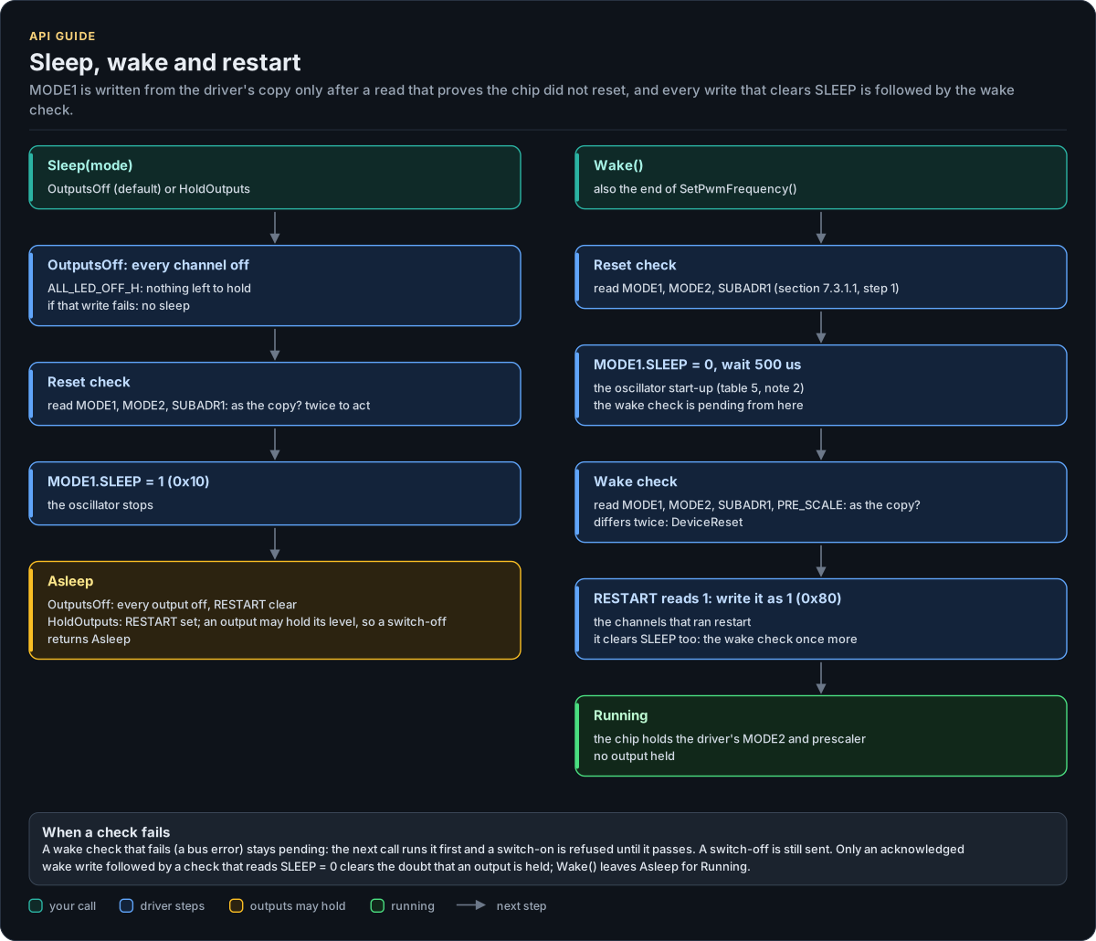
Figure description and sources
Left, the two ways to sleep. SleepMode::OutputsOff writes ALL_LED_OFF first (the orderly shutdown of section 7.3.1.1), so nothing is held and RESTART stays clear; SleepMode::HoldOutputs sleeps with the channels running, so RESTART sets and an output may hold its level while the oscillator is off. Both read MODE1 and MODE2 first, the reset check, before MODE1 is written from the driver's copy. Right, the wake: the reset check, MODE1 with SLEEP = 0, the oscillator start-up wait, then the wake check (MODE1, MODE2 and PRE_SCALE compared with the copy); when RESTART reads 1 it is written back as 1, which restarts the channels, and because that write clears SLEEP too the wake check runs once more. SetPwmFrequency() is a sleep, a PRE_SCALE write and read-back, and this wake. The band at the bottom says what a failed check leaves.
Drawn from: src/pca9685.ipp Sleep, Wake, wakeSequence, completeWakeCheck, verifyRunning, SetPwmFrequency, changePrescale; inc/pca9685_registers.hpp kMode1Sleep, kMode1Restart; inc/pca9685_types.hpp kOscillatorStartUs; figure module docs/diagrams/figures/sleep-restart.py.
The output path
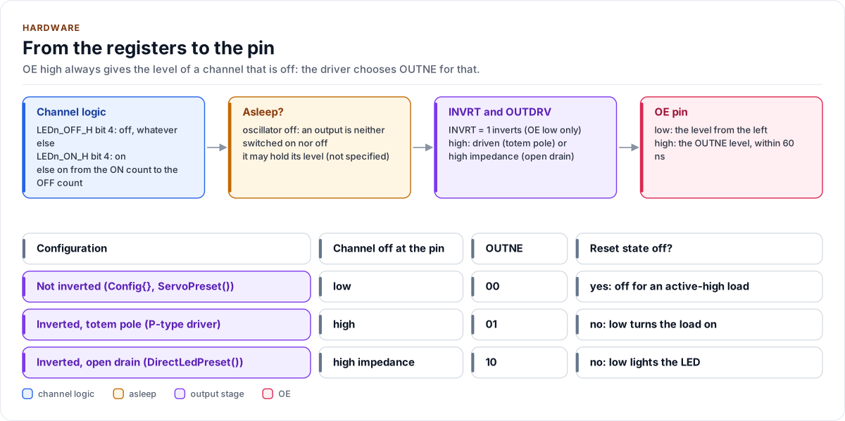
Figure description and sources
Left to right, what decides the level of output LEDn (tables 6, 7 and 11). The channel logic is off when LEDn_OFF_H bit 4 is set, whatever else the registers hold; otherwise on when LEDn_ON_H bit 4 is set; otherwise asserted from the ON count to the OFF count of the 12-bit counter. Asleep, the oscillator is off and an output can be neither switched on nor off. INVRT inverts the logic while OE is low; OUTDRV makes a high level a driven high (totem pole) or high impedance (open drain). OE high replaces everything with the OUTNE level, which the driver sets to the level of a channel that is off. The table at the bottom gives that level for each configuration, and whether the reset state (not inverted, OUTNE = 00) is off for the load.
Drawn from: inc/pca9685.hpp OffLevelOutne, Mode2Value; inc/pca9685_registers.hpp kOutneLow, kOutneHigh, kOutneHiZ, kLedFull; src/pca9685.ipp applyOne; figure module docs/diagrams/figures/output-path.py.
Design choices
- Every output off before anything else. The start-up's first frames switch everything off, in a form that works whatever an earlier run left (MODE1.AI set or clear, OCH 0 or 1, asleep or awake), and each is sent even if one before it failed.
- The identity check is a read-back. The chip has no ID register; MODE1, MODE2, PRE_SCALE and all 16 channels must read back what was written, which a floating, stuck or looped line cannot produce.
- A reset sentinel the driver controls. MODE1.AI is set by the driver and cleared only by a reset; MODE2,
EXTCLK and PRE_SCALE are written only at start-up and by
SetPwmFrequency(). The simplest provable rule: any of them back at its reset value while the copy differs is a reset. - No wake without a check. Every MODE1 write that clears SLEEP is followed by a read of MODE1, MODE2 and PRE_SCALE; a reset chip asleep cannot switch an output on, so it is harmless until it is woken.
- A failed write is a possible write. The copy records which channels may hold old, new or mixed values; a switch-on that depends on such a value is refused; a switch-off never is.
- OCH = 0 only. All bytes of a transfer reach the outputs at its STOP, so a bank of channels changes together and a NACK leaves exactly the bytes before it, applied once.
- OUTNE chosen by the driver. OE high always gives the level of a channel that is off.
- CRTP, not virtual functions. The port is a template parameter constrained by the
I2cPortconcept, so every call is resolved at compile time and a missing hook is a compile error that names it. - No I/O in the constructor, one error type, no heap, no exceptions, no RTTI, no
std::function, noprintf.
Source map
| You want | Read |
|---|---|
| The public API | inc/pca9685.hpp |
| How a call is implemented | src/pca9685.ipp |
| Register addresses and bits | inc/pca9685_registers.hpp |
| The arithmetic and the configuration | inc/pca9685_types.hpp |
| The port contract | inc/pca9685_i2c_interface.hpp |
Next: Contract.